CLI: Example for Configuring L2TP VPN (Local Authentication) in the Client-Initiated Scenario
This section provides an example for configuring L2TP VPN in the client-initiated scenario. In the scenario, mobile users use the SecoClient to access the enterprise intranet through L2TP VPN tunnels.
Networking Requirements
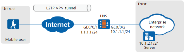
Data Planning
Item |
Data |
|
|---|---|---|
LNS |
Interface |
Interface ID: GigabitEthernet 0/0/1 IP address: 1.1.1.1/24 Security zone: Untrust Interface ID: GigabitEthernet 0/0/2 IP address: 10.1.1.1/24 Security zone: Trust |
L2TP configuration |
Peer tunnel name: client User name: user0001 Password: Password123 Tunnel authentication password: Hello123 Address pool: 172.16.1.2 to 172.16.1.100 NOTE:
If the intranet server IP address and address pool addresses are on different network segments, configure a route on the intranet server to an address in the address pool. |
|
Mobile user |
User name: user0001 Password: Password123 |
|
Procedure
- Configure the LNS.
- Configure the authentication domain and user information.
- Configure the authentication domain and users.

To implement user name-based policy control on L2TP access users, you must specify the internetaccess parameter.
[LNS-aaa] domain default
[LNS-aaa-domain-default] service-type l2tp
- Configure a branch user and the user group of the user.
[LNS] user-manage group /default/research
[LNS-usergroup-/default/research] quit
[LNS] user-manage user user0001
[LNS-localuser-user0001] parent-group /default/research
[LNS-localuser-user0001] password Password123
[LNS-localuser-user0001] quit
- Configure the authentication domain and users.
- Configure the authentication domain and user information.
- Configure the SecoClient at the mobile user side.
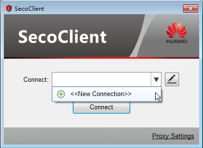
- Open the SecoClient and access the home page.
Select New Connection from the Connect drop-down list.
- Set L2TP VPN connection parameters.
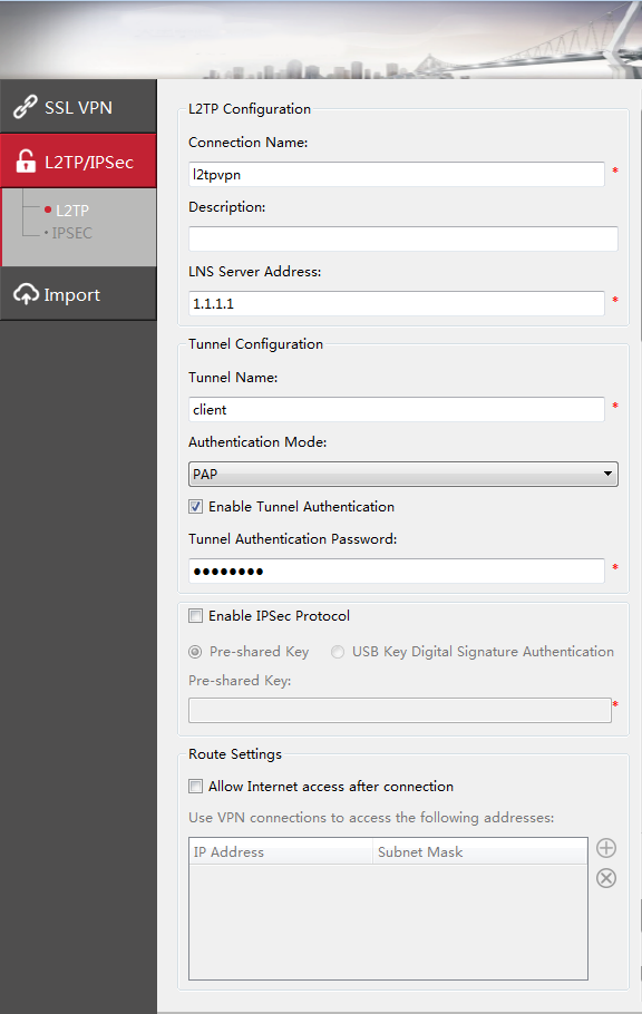
In the New Connection navigation tree, select L2TP/IPSec. Set connection parameters and click OK.
The tunnel authentication password is Hello123.
- Log in to the L2TP VPN gateway.
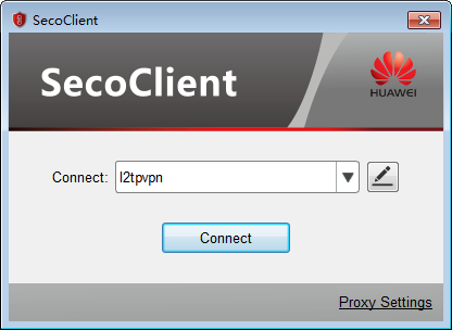
- Select the created L2TP VPN connection from the Connect drop-down list and click Connect.
- On the login page, enter the user name and password.
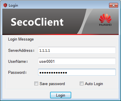
- Click Login to initiate a VPN connection request.
A message on a VPN access success will be displayed on the web UI. After the connection is established, mobile users can access intranet resources as intranet users.
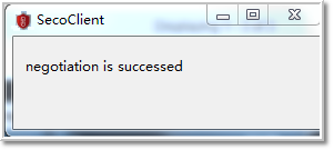
- Select the created L2TP VPN connection from the Connect drop-down list and click Connect.
- Open the SecoClient and access the home page.
Verification
- Mobile users can properly access intranet servers of the headquarters.
Check L2TP tunnel establishment information on the LNS. The command output on the LNS is used as an example.
- Run the display l2tp tunnel command to check L2TP tunnel information. According to the command output, an L2TP tunnel is established successfully.
[LNS] display l2tp tunnel
L2TP::Total Tunnel: 1

 LocalTID RemoteTID RemoteAddress    Port   Sessions RemoteName  VpnInstance
 ------------------------------------------------------------------------------
 2        1         2.2.2.2          61535   1         client
 ------------------------------------------------------------------------------
  Total 1, 1 printed
Run the display l2tp session command to check L2TP session information. According to the command output, an L2TP session is established successfully.
[LNS] display l2tp session
L2TP::Total Session: 1

  LocalSID  RemoteSID  LocalTID   RemoteTID  UserID  UserName    VpnInstance
 ------------------------------------------------------------------------------
  119       32         2           1         9689    user0001
 ------------------------------------------------------------------------------
  Total 1, 1 printed
- Run the display l2tp tunnel command to check L2TP tunnel information. According to the command output, an L2TP tunnel is established successfully.
Configuration Scripts
#
sysname LNS
#
 l2tp enable
 l2tp domain suffix-separator @
#
ip pool pool
 section 0 172.16.1.2 172.16.1.100
#
aaa
 service-scheme l2tp
  ip-pool pool
 domain default
  service-type l2tp
#
l2tp-group 1
 allow l2tp virtual-template 1 remote client
 tunnel password cipher %$%$cgc'GPcWL#hp3EC;K[nM[QH~%$%$
#
interface Virtual-Template1
 ppp authentication-mode pap
 remote service-scheme l2tp
 ip address 172.16.1.1 255.255.255.0
#
interface GigabitEthernet 0/0/1
 undo shutdown
 ip address 1.1.1.1 255.255.255.0
#
interface GigabitEthernet 0/0/2
 undo shutdown
 ip address 10.1.1.1 255.255.255.0
#
firewall zone trust
 set priority 85
 add interface GigabitEthernet 0/0/2
#
firewall zone untrust
 set priority 5
 add interface GigabitEthernet 0/0/1
#
firewall zone dmz
 set priority 50
 add interface Virtual-Template1
#
ip route-static 0.0.0.0 0.0.0.0 1.1.1.2
#
security-policy
  rule name service_td
    source-zone trust
    destination-zone dmz
    source-address 10.1.2.0 24
    destination-address 172.16.1.0 24
    action permit
  rule name service_dt
    source-zone dmz
    destination-zone trust
    source-address 172.16.1.0 24
    destination-address 10.1.2.0 24
    action permit
  rule name l2tp_ul
    source-zone untrust
    destination-zone local
    destination-address 1.1.1.0 24
    action permit
# The following configurations for creating users are stored in the database, not described in the configuration file.
user-manage user user0001
 parent-group /default/research
 password **********
 undo multi-ip online enable