Web: Example for Configuring NAT No-PAT for Intranet Users to Access the Internet (a Specific Destination Server)
This section provides an example for configuring NAT No-PAT for intranet users to access the Internet.
Networking Requirements
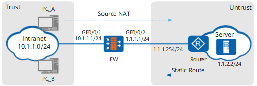
The FW serves as the security gateway at the border of a studio. A source NAT policy must be configured on the FW to allow users in network 10.1.1.0/24 to access the Internet. Considering that a small number of users need to access a specific destination server on the Internet, the FW shall use NAT No-PAT to perform one-to-one address translation for private addresses that match NAT policies. The studio applied for six IP addresses (1.1.1.10 to 1.1.1.15) from the ISP for address translation. Figure 1 shows the network environment. The router is the access gateway provided by the ISP.
Data Planning
Item |
Data |
Description |
|
|---|---|---|---|
GigabitEthernet 0/0/1 |
IP address: 10.1.1.1/24 Security zone: trust |
Set the default gateway address on each intranet host to 10.1.1.1. |
|
GigabitEthernet 0/0/2 |
IP address: 1.1.1.1/24 Security zone: untrust |
1.1.1.1/24 is a public address provided by the ISP. |
|
Intranet segment that is allowed to access the Internet |
10.1.1.0/24 |
- |
|
Public addresses mapped to private addresses |
1.1.1.10 to 1.1.1.15 |
Only a small number of users need to access the Internet. Therefore, NAT NO-PAT is configured on the FW. |
|
Destination address |
1.1.2.2 |
- |
|
Routing information |
FW's default route |
Destination address: 0.0.0.0 Next hop address: 1.1.1.254 |
Configure a default route on the FW to direct intranet traffic to the ISP network. |
Router's static route |
Destination address: 1.1.1.10 to 1.1.1.15 Next hop address: 1.1.1.1 |
The public addresses mapped to private addresses are not assigned to physical ports. As a result, the router cannot use a routing protocol to discover routes to the public addresses. Ask the ISP network administrator to configure a static route destined for the network segment address of the address pool on the router. |
|
Configuration Roadmap
The configuration roadmap is as follows:
- Assign IP addresses to interfaces, add the interfaces to security zones, and configure network connectivity.
- Configure a security policy to allow a specific intranet segment to access the Internet.
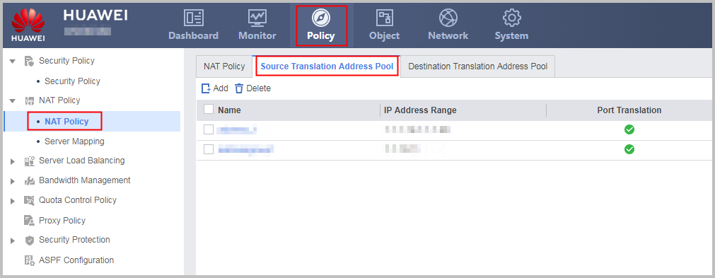
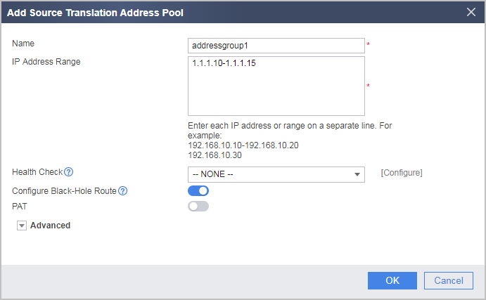
- Configure a NAT address pool and disable port translation.
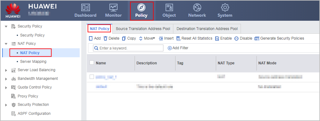
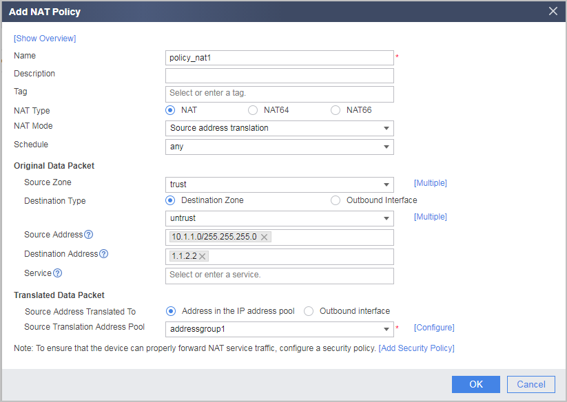
- Configure source NAT policy 1 and a destination-based rule (destination IP address or security zone), so that source address translation is automatically performed when a specified network segment on the private network accesses the destination server.
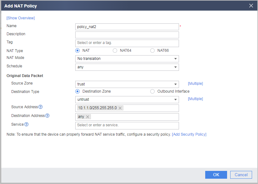
- Configure source NAT policy 2 and a destination-based rule (destination IP address or security zone), so that source address translation is not performed when a specified network segment on the private network accesses a non-destination server. If the traffic for which translation does not need to be performed is not accurately configured, NAT translation is performed not only when a user (IP address) matches NAT policy 1 but also when the user accesses a non-destination server.
- Configure a default route on the FW to direct intranet traffic to the ISP router.
- Configure the IP address of the FW interface connected to the intranet as the default gateway address on each intranet host so that intranet traffic is directed to the FW when intranet hosts access the Internet.
- Configure a static route on the ISP router for forwarding Internet traffic to the FW.
Procedure
- Set IP addresses for interfaces on the FW and assign the interfaces to security zones.
- Set the IP address of GigabitEthernet 0/0/1 and assign the interface to a security zone.
- Set the IP address of GigabitEthernet 0/0/2 and assign the interface to a security zone.
- Configure a security policy to allow users on a specific network to access the Internet.
- Configure a NAT address pool and a NAT policy.
- Configure a default route on the FW, so that traffic from the private network can be forwarded to the ISP router.
- On each PC, configure the IP address of the FW interface connected to the intranet as the default gateway address to direct intranet traffic to the FW. The detailed configuration process is omitted.
- On the router, configure a static route destined for the network segment of the address pool (1.1.1.10 to 1.1.1.15) and set the next-hop address of the static route to 1.1.1.1 so that Internet traffic destined for the intranet server can be forwarded by the FW.
Contact your ISP administrator to perform this step.

Configuration Scripts
Configuration script for the FW:
#
 sysname FW
#
interface GigabitEthernet0/0/1
 undo shutdown
 ip address 10.1.1.1 255.255.255.0
#
interface GigabitEthernet0/0/2
 undo shutdown
 ip address 1.1.1.1 255.255.255.0
#
firewall zone trust
 set priority 85
 add interface GigabitEthernet0/0/1
#
firewall zone untrust
 set priority 5
 add interface GigabitEthernet0/0/2
#
 ip route-static 0.0.0.0 0.0.0.0 1.1.1.254
#
nat address-group addressgroup1 0
 mode no-pat global
 route enable
 section 0 1.1.1.10 1.1.1.15
#
security-policy
  rule name policy1
    source-zone trust
    destination-zone untrust
    source-address 10.1.1.0 24
    action permit
#
nat-policy
  rule name policy_nat1
    source-zone trust
    destination-zone untrust
    source-address 10.1.1.0 24
    destination-address 1.1.2.2 32
    action source-nat address-group addressgroup1
  rule name policy_nat2
    source-zone trust
    destination-zone untrust
    source-address 10.1.1.0 24
    destination-address any
    action no-nat
#
return