Web: Example for Configuring Destination NAT for Mobile Phone Users to Access Wireless Networks (Translating Public Addresses Randomly Into Addresses in the Destination Address Pool)
This section provides an example for configuring destination NAT for mobile phone users to access wireless networks.
Networking Requirements
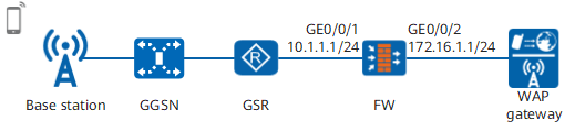
Mobile phone users need to access the Internet by logging in to a WAP gateway. If the IP address of a mobile phone for accessing the Internet is not that of the WAP gateway, configure rules on the FW to translate the destination IP address of the access request into the IP address of the WAP gateway.
As shown in Figure 1, the default gateway address of the mobile phone is 1.1.1.1, but that provided by the carrier is 2.2.2.2. The FW needs to change the gateway address of the packets from the mobile phone to the carrier gateway.
Data Planning
Item |
Data |
Description |
|
|---|---|---|---|
GigabitEthernet 0/0/1 |
IP address: 10.1.1.1/24 Security zone: Trust |
- |
|
GigabitEthernet 0/0/2 |
IP address: 172.16.1.1/24 Security zone: Untrust |
- |
|
Destination NAT |
Destination IP address pool: 2.2.2.2 |
- |
|
Security policy |
Source zone: Trust Destination zone: Untrust Destination address: 2.2.2.2 |
Permits the traffic destined to the gateway address of the carrier to pass through the FW. | |
Configuration Roadmap
- Set interface IP addresses and assign the interfaces to security zones.
- Configure destination NAT to translate destination addresses.
- Configure a security policy to permit the traffic from mobile phone users to pass through the FW.
Procedure
- Set IP addresses for interfaces on the FW and assign the interfaces to security zones.
- Set the IP address of GigabitEthernet 0/0/1 and assign the interface to a security zone.
- Set the IP address of GigabitEthernet 0/0/2 and assign the interface to a security zone.
- Configure NAT address pools and NAT policies.
-
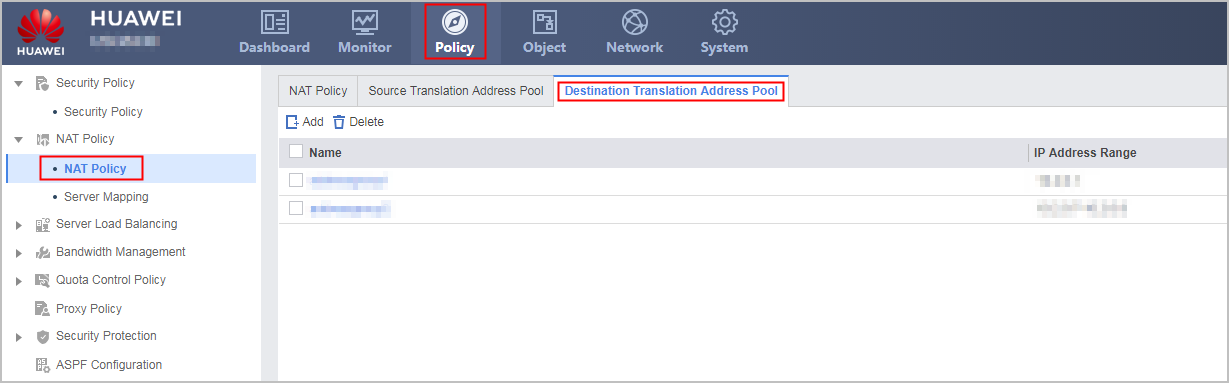
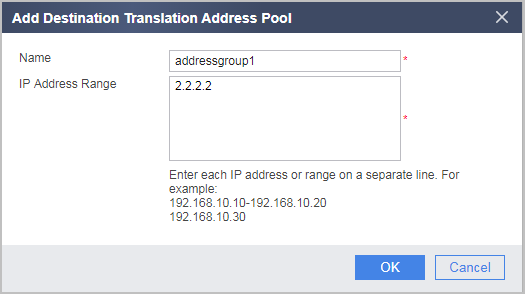
In Destination Translation Address Pool List, click Add and configure a NAT address pool based on the following parameters.

You can configure multiple addresses in the address pool so that public addresses can be randomly translated to addresses in the address pool. In this section, a gateway address is used as an example.
-
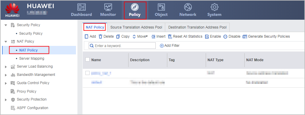
In NAT Policy List, click Add and configure a NAT policy based on the following parameters.
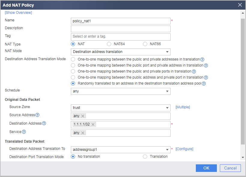
-
- Configure a black-hole route on the FW, so that traffic from intranet servers can be forwarded to the ISP router.
- Configure a security policy.

Verification
- Mobile phone users can access the Internet, indicating that destination NAT is configured successfully.
- Run the display firewall session table verbose command to view the entry whose destination address is 1.1.1.1 for detailed NAT information.
<FW> display firewall session table verbose
Current Total Sessions : 1
 http  VPN:public --> public  10.1.1.100:4194-->1.1.1.1:2048[2.2.2.2:2048]
The gateway address of the packets from mobile phone users is changed by the FW from 1.1.1.1 to the carrier gateway address (2.2.2.2). The content in [] is the translated carrier gateway address.
Configuration Scripts
Configuration script for the FW:
#
 sysname FW
#
interface GigabitEthernet0/0/1
 undo shutdown
 ip address 10.1.1.1 255.255.255.0
#
interface GigabitEthernet 0/0/2
 undo shutdown
 ip address 172.16.1.1 255.255.255.0
#
firewall zone trust
 set priority 85
 add interface GigabitEthernet0/0/1
#
firewall zone untrust
 set priority 5
 add interface GigabitEthernet 0/0/2
#
 ip route-static 1.1.1.1 255.255.255.255 NULL0
#
destination-nat address-group addressgroup1
 section 2.2.2.2 2.2.2.2
#
security-policy
  rule name policy1
    source-zone trust
    destination-zone untrust
    destination-address 2.2.2.2 32
    action permit
#
nat-policy
 rule name policy_nat1
  source-zone trust
  destination-address 1.1.1.1 32
  action destination-nat address-group addressgroup1
#
return