CLI: Example for Configuring Destination NAT for Internet Users to Access Intranet Servers (One-to-one Mappings Between Public and Private Interfaces)
This section provides an example for configuring destination NAT for Internet users to access intranet servers.
Networking Requirements
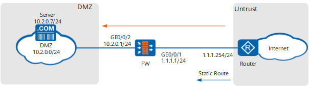
The FW serves as a security gateway at the border of an enterprise network. Destination NAT needs to be configured on the FW so that intranet servers can provide different services externally. In addition to the IP addresses of Internet interfaces, the enterprise applies for another public IP address (1.1.10.10) for the intranet server to provide services. Figure 1 illustrates the networking. The router is an access gateway on the ISP network.
Data Planning
Item |
Data |
Description |
|
|---|---|---|---|
GigabitEthernet 0/0/1 |
IP address: 1.1.1.1/24 Security zone: Untrust |
1.1.1.1/24 is a public address provided by the ISP. |
|
GigabitEthernet 0/0/2 |
IP address: 10.2.0.1/24 Security zone: DMZ |
Intranet servers use 10.2.0.1 as the default gateway address. |
|
Destination NAT |
Destination address before translation: 1.1.10.10 Destination address after translation: 10.2.0.7 Ports before translation: 2000 and 2001 Port number after translation: 80 and 81 |
When an Internet user accesses address 1.1.10.10, the FW that has the destination NAT function enabled can send traffic to the intranet server. |
|
Routing information |
Default route |
Destination address: 0.0.0.0 Next hop address: 1.1.1.254 |
Configure a default route defined for the ISP router on the FW to direct intranet traffic to the router. |
Configuration Roadmap
The configuration roadmap is as follows:
- Assign IP addresses to interfaces, add the interfaces to security zones, and configure network connectivity.
- Configure a security policy for traffic between Internet users and intranet servers.
Configure the destination NAT function so that when an Internet user accesses address 1.1.10.10, the FW can send traffic to the intranet server.
- Configure a default route on the FW to direct intranet traffic to the ISP router.
- Configure a blackhole route on the FW to prevent routing loops between the FW and router.
- Configure static routes destined for public addresses of intranet servers on the router.
Procedure
- Assign IP addresses to interfaces, add the interfaces to security zones, and configure network connectivity.
# Assign an IP address to GigabitEthernet 0/0/1.
<FW> system-view
[FW] interface GigabitEthernet 0/0/1
[FW-GigabitEthernet 0/0/1] ip address 1.1.1.1 24
[FW-GigabitEthernet 0/0/1] quit
# Assign an IP address to GigabitEthernet 0/0/2.
[FW] interface GigabitEthernet 0/0/2
[FW-GigabitEthernet 0/0/2] ip address 10.2.0.1 24
[FW-GigabitEthernet 0/0/2] quit
# Add GigabitEthernet 0/0/1 to the Untrust zone.
[FW] firewall zone untrust
[FW-zone-untrust] add interface GigabitEthernet 0/0/1
[FW-zone-untrust] quit
# Add GigabitEthernet 0/0/2 to the DMZ zone.
[FW] firewall zone dmz
[FW-zone-dmz] add interface GigabitEthernet 0/0/2
[FW-zone-dmz] quit
- Configure a security policy for traffic between Internet users and intranet servers.
[FW] security-policy
[FW-policy-security] rule name policy1
[FW-policy-security-rule-policy1] source-zone untrust
[FW-policy-security-rule-policy1] destination-zone dmz
[FW-policy-security-rule-policy1] destination-address 10.2.0.0 24
[FW-policy-security-rule-policy1] action permit
[FW-policy-security-rule-policy1] quit
[FW-policy-security] quit
- Configure a destination NAT address pool.
[FW] destination-nat address-group addressgroup1
[FW-dnat-address-group-addressgroup1] section 10.2.0.7 10.2.0.7
[FW-dnat-address-group-addressgroup1] quit
- Configure a NAT policy.
[FW] nat-policy
[FW-policy-nat] rule name policy_nat1
[FW-policy-nat-rule-policy_nat1] source-zone untrust
[FW-policy-nat-rule-policy_nat1] destination-address 1.1.10.10 32
[FW-policy-nat-rule-policy_nat1] service protocol tcp destination-port 2000 to 2001
[FW-policy-nat-rule-policy_nat1] action destination-nat static port-to-port address-group addressgroup1 80 to 81
[FW-policy-nat-rule-policy_nat1] quit
[FW-policy-nat] quit
- Configure black-hole routes destined to the destination address of traffic to prevent routing loops.
[FW] ip route-static 1.1.10.10 255.255.255.255 NULL0 - Enable NAT ALG for FTP.
[FW] firewall interzone dmz untrust
[FW-interzone-dmz-untrust] detect ftp
[FW-interzone-dmz-untrust] quit
- Configure a default route to direct intranet traffic to the ISP router.
[FW] ip route-static 0.0.0.0 0.0.0.0 1.1.1.254 - On the router, configure a static route, in which the destination address is 1.1.10.10 and the next-hop address is 1.1.1.1. The router directs traffic destined for 1.1.10.10 to the FW based on the static route so that the FW can forward the traffic to the intranet server.
Contact your ISP administrator to perform this step.
Configuration Scripts
Configuration script for the FW:
#
 sysname FW
#
interface GigabitEthernet0/0/1
 undo shutdown
 ip address 1.1.1.1 255.255.255.0
#
interface GigabitEthernet0/0/2
 undo shutdown
 ip address 10.2.0.1 255.255.255.0
#
firewall zone untrust
 set priority 5
 add interface GigabitEthernet0/0/1
#
firewall zone dmz
 set priority 50
 add interface GigabitEthernet0/0/2
#
firewall interzone dmz untrust
 detect ftp
#
 ip route-static 0.0.0.0 0.0.0.0 1.1.1.254
 ip route-static 1.1.10.10 255.255.255.255 NULL0
#
destination-nat address-group addressgroup1 0
 section 10.2.0.7 10.2.0.7
#
security-policy
  rule name policy1
    source-zone untrust
    destination-zone dmz
    destination-address 10.2.0.0 24
    action permit
#
nat-policy
  rule name policy_nat1
    source-zone untrust
    destination-address 1.1.10.10 32
    service protocol tcp destination-port 2000 to 2001
    action destination-nat static port-to-port address-group addressgroup1 80 to 81
#
return