CLI: Example for Configuring Source NAT in a Load Balancing Scenario (Active and Standby Devices Use Different Address Pools)
Networking Requirements
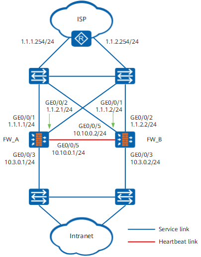
On the network shown in Figure 1, the service interfaces of two FWs work at Layer 3 and are directly connected to switches.
The FWs are required to work in load balancing mode. In normal cases, FW_A forwards traffic from Dept. A (IP address range: 10.3.0.51 to 10.3.0.100), and FW_B forwards traffic from Dept. B (IP address range: 10.3.0.101 to 10.3.0.150). If either FW fails, the other FW forwards all traffic to ensure service continuity.
To enable private network users to access the Internet, you need to configure a source NAT policy on FW_A and FW_B.
The address pool including address 1.1.1.4 is created on FW_A to provide post-NAT public addresses for PCs from Dept. A (IP address range: 10.3.0.51 to 10.3.0.100), and the address pool including address 1.1.2.4 is created on FW_B to provide post-NAT public addresses for PCs from Dept. B (IP address range: 10.3.0.101 to 10.3.0.150).

In this load balancing networking, FWs connect to switches in both upstream and downstream directions. On live networks, you must determine whether VRRP groups are required based on the upstream and downstream devices and interfaces. The Source NAT configuration remains unchanged.
This example does not apply when uplink interfaces connect to different ISP networks.
Data Planning
Item |
FW_A |
FW_B |
|
|---|---|---|---|
Interface |
GigabitEthernet 0/0/1 IP address: 1.1.1.1/24 Security zone: Untrust GigabitEthernet 0/0/2 IP address: 1.1.2.1/24 Security zone: Untrust GigabitEthernet 0/0/3 IP address: 10.3.0.1/24 Security zone: Trust GigabitEthernet 0/0/5 IP address: 10.10.0.1/24 Security zone: DMZ |
GigabitEthernet 0/0/1 IP address: 1.1.1.2/24 Security zone: Untrust GigabitEthernet 0/0/2 IP address: 1.1.2.2/24 Security zone: Untrust GigabitEthernet 0/0/3 IP address: 10.3.0.2/24 Security zone: Trust GigabitEthernet 0/0/5 IP address: 10.10.0.2/24 Security zone: DMZ |
|
VRRP Groups |
On GigabitEthernet 0/0/1, configure VRRP group 1 and add it to the active VGMP group. On GigabitEthernet 0/0/2, configure VRRP group 1 and add it to the standby VGMP group. On GigabitEthernet 0/0/3, configure VRRP group 3 and add it to the active VGMP group, configure VRRP group 4 and add it to the standby VGMP group. Virtual address of the VRRP group 1: 1.1.1.3/24 Virtual address of the VRRP group 2: 1.1.2.3/24 Virtual address of the VRRP group 3: 10.3.0.3/24 Virtual address of the VRRP group 4: 10.3.0.4/24 |
On GigabitEthernet 0/0/1, configure VRRP group 1 and add it to the standby VGMP group. On GigabitEthernet 0/0/2, configure VRRP group 1 and add it to the active VGMP group. On GigabitEthernet 0/0/3, configure VRRP group 3 and add it to the standby VGMP group, configure VRRP group 4 and add it to the active VGMP group. Virtual address of the VRRP group 1: 1.1.1.3/24 Virtual address of the VRRP group 2: 1.1.2.3/24 Virtual address of the VRRP group 3: 10.3.0.3/24 Virtual address of the VRRP group 4: 10.3.0.4/24 |
|
Configuration Roadmap
- Assign IP addresses to interfaces, add the interfaces to security zones, and configure network connectivity on FW_A and FW_B.
- Configure IP-Link on FW_A to detect faults on the link connecting FW_A to the router. Configure IP-Link on FW_B to detect faults on the link connecting FW_B to the router.
- Configure two default routes on FW_A. Set the next hop of one default route to 1.1.1.254. Set the next hop of the other default route to 1.1.2.254, bind this default route to IP-Link, and set a higher preference. Configure two default routes on FW_A. Set the next hop of one default route to 1.1.2.254. Set the next hop of the other default route to 1.1.1.254, bind this default route to IP-Link, and set a higher preference.
- Configure hot standby on FW_A and FW_B. To be specific, configure VRRP groups, specify heartbeat interfaces, and enable quick session backup.
- Configure a security policy on FW_A to allow intranet users to access the Internet. The security policy configured on FW_A is automatically backed up to FW_B.
- Configure two NAT address pools (addressgroup1 and addressgroup2) on FW_A. The NAT address pools configured on FW_A are automatically backed up to FW_B.
- Configure a Source NAT policy on FW_A to translate the source addresses of users in department A (10.3.0.51-10.3.0.100) into addresses in the address pool addressgroup1 and translate the source addresses of users in department B (10.3.0.101-10.3.0.150) into addresses in the address pool addressgroup2 when they access the Internet. The Source NAT policy configured on FW_A is automatically backed up to FW_B.
- Configure default routes on intranet PCs to set the next hop of department A to the virtual IP address 10.3.0.3 of VRRP group 3 and the next hop of department B to the virtual IP address 10.3.0.4 of VRRP group 4.
- Configure two static routes on the router. For one static route, set the destination address to an address in the address pool addressgroup1 and the next hop to the virtual IP address 1.1.2.3 of VRRP group 2. For the other static route, set the destination address to an address in the address pool addressgroup2 and the next hop to the virtual IP address 1.1.1.3 of VRRP group 1. If one link fails, traffic can travel along the other link.
Procedure
- Set interface IP addresses and assign the interfaces to security zones.
- Configure IP-Link on FW_A to detect faults on the link connecting FW_A to the router. Configure IP-Link on FW_B to detect faults on the link connecting FW_B to the router.
# Configuring IP-Link on FW_A.
[FW_A] ip-link check enable
[FW_A] ip-link name link1
[FW_A-iplink-link1] destination 1.1.1.254 interface GigabitEthernet 0/0/1
# Configuring IP-Link on FW_B.
[FW_B] ip-link check enable
[FW_B] ip-link name link2
[FW_B-iplink-link2] destination 1.1.2.254 interface GigabitEthernet 0/0/2
- Configure two default routes on FW_A. Set the next hop of one default route to 1.1.1.254. Set the next hop of the other default route to 1.1.2.254, bind this default route to IP-Link, and set a
higher preference. Configure two default routes on FW_A. Set the next hop of one default route to 1.1.2.254. Set the next hop of the other default route to 1.1.1.254, bind this default route to IP-Link, and
set a higher preference.
# Configure default routes on FW_A.
[FW_A] ip route-static 0.0.0.0 0.0.0.0 1.1.1.254
[FW_A] ip route-static 0.0.0.0 0.0.0.0 1.1.2.254 preference 50 track ip-link link1
# Configure default routes on FW_B.
[FW_B] ip route-static 0.0.0.0 0.0.0.0 1.1.2.254
[FW_B] ip route-static 0.0.0.0 0.0.0.0 1.1.1.254 preference 50 track ip-link link2
- Configure hot standby.
- Configure hot standby on FW_A.
# Configure VRRP groups.
[FW_A] interface GigabitEthernet 0/0/1
[FW_A-GigabitEthernet0/0/1] vrrp vrid 1 virtual-ip 1.1.1.3 active
[FW_A-GigabitEthernet0/0/1] quit
[FW_A] interface GigabitEthernet 0/0/2
[FW_A-GigabitEthernet0/0/2] vrrp vrid 2 virtual-ip 1.1.2.3 stanby
[FW_A-GigabitEthernet0/0/2] quit
[FW_A] interface GigabitEthernet 0/0/3
[FW_A-GigabitEthernet0/0/3] vrrp vrid 3 virtual-ip 10.3.0.3 active
[FW_A-GigabitEthernet0/0/3] vrrp vrid 4 virtual-ip 10.3.0.4 standby
[FW_A-GigabitEthernet0/0/3] quit
# Specify a heartbeat interface.
[FW_A] hrp interface GigabitEthernet 0/0/5 remote 10.10.0.2
# Enable quick session backup.
[FW_A] hrp mirror session enable When the FWs work in load-balancing mode, the forward and return packets may pass through different FWs. To ensure service continuity, you must enable quick session backup to ensure that the session information on one FW is synchronized to the otherFW.# Enable hot standby.
[FW_A] hrp enable
- Configure hot standby on FW_A.
- Configure a security policy on FW_A to allow intranet users to access the Internet.
Security policies configured on FW_A are automatically backed up to FW_B.
HRP_M[FW_A] security-policy
HRP_M[FW_A-policy-security] rule name policy_sec_1
HRP_M[FW_A-policy-security-rule-policy_sec_1] source-zone trust
HRP_M[FW_A-policy-security-rule-policy_sec_1] source-address 10.3.2.0 24
HRP_M[FW_A-policy-security-rule-policy_sec_1] action permit
HRP_M[FW_A-policy-security-rule-policy_sec_1] quit
HRP_M[FW_A-policy-security] quit
- Configure NAT address pools and permit port conversion to reuse public network addresses.
Create address pools addressgroup1 (1.1.1.4-1.1.1.4) and addressgroup2 (1.1.1.13-1.1.1.15) on FW_A. The NAT address pools configured on FW_A are automatically backed up to FW_B.
HRP_M[FW_A] nat address-group addressgroup1
HRP_M[FW_A-nat-address-group-addressgroup1] section 0 1.1.1.4 1.1.1.4
HRP_M[FW_A-nat-address-group-addressgroup1] mode pat
HRP_M[FW_A-nat-address-group-addressgroup1] quit
HRP_M[FW_A] nat address-group addressgroup2
HRP_M[FW_A-nat-address-group-addressgroup2] section 1 1.1.2.4 1.1.2.4
HRP_M[FW_A-nat-address-group-addressgroup2] mode pat
HRP_M[FW_A-nat-address-group-addressgroup2] quit
- Configure NAT policies to allow intranet users to access the Internet by using post-NAT public IP addresses.
Configure a Source NAT policy on FW_A to translate the source addresses of users in department A (10.3.0.51-10.3.0.100) into addresses in the address pool addressgroup1 and translate the source addresses of users in department B (10.3.0.101-10.3.0.150) into addresses in the address pool addressgroup2 when they access the Internet. The Source NAT policy configured on FW_A is automatically backed up to FW_B.
Configure a Source NAT policy on FW_A to translate the private addresses of PCs on network segment 10.3.1.0/24 that attempt to access the Internet into public addresses in the address pool addresspool1.
HRP_M[FW_A] nat-policy
HRP_M[FW_A-policy-nat] rule name policy_nat_1
HRP_M[FW_A-policy-nat-policy_nat_1] source-address range 10.3.0.51 10.3.0.100
HRP_M[FW_A-policy-nat-policy_nat_1] source-zone trust
HRP_M[FW_A-policy-nat-policy_nat_1] destination-zone untrust
HRP_M[FW_A-policy-nat-policy_nat_1] action source-nat address-group addressgroup1
HRP_M[FW_A-policy-nat-policy_nat_1] quit
HRP_M[FW_A-policy-nat] rule name policy_nat_2
HRP_M[FW_A-policy-nat-policy_nat_2] source-address range 10.3.0.101 10.3.0.150
HRP_M[FW_A-policy-nat-policy_nat_2] source-zone trust
HRP_M[FW_A-policy-nat-policy_nat_2] destination-zone untrust
HRP_M[FW_A-policy-nat-policy_nat_2] action source-nat address-group addressgroup2
HRP_M[FW_A-policy-nat-policy_nat_2] quit
HRP_M[FW_A-policy-nat] quit
- Configure default routes for intranet PCs, so that traffic from department A is forwarded through FW_A, and traffic from department B is forwarded through FW_B when both FWs work properly.
Configure default routes on intranet PCs to set the next hop of department A to the virtual IP address 10.3.0.3 of VRRP group 3 and the next hop of department B to the virtual IP address 10.3.0.4 of VRRP group 4.
The next-hop address of the default route on PCs of network segment 10.3.1.0/24 is IP address 10.3.1.2 of VRRP group 3, and the next-hop address of the default route on PCs of network segment 10.3.2.0/24 is IP address 10.3.2.2 of VRRP group 4.
- Configure two static routes on the router. For one static route, set the destination address to an address in the address pool addressgroup1 and the next hop to the virtual IP address 1.1.2.3 of VRRP group 2. For the other static route,
set the destination address to an address in the address pool addressgroup2 and the next hop to the virtual IP address 1.1.1.3 of VRRP group 1. If one link fails, traffic can travel along the other link.
You need to contact the ISP network administrator to configure these static routes.
Configuration Verification
Run the display hrp state command on FW_A and FW_B respectively to check the HRP status. The following command output shows that HRP is configured successfully.
HRP_M[FW_A] display hrp state Role: active, peer: active Running priority: 49010, peer: 49010 Backup channel usage: 3% Stable time: 0 days, 5 hours, 1 minutesHRP_S[FW_B] display hrp state Role: active, peer: active Running priority: 49010, peer: 49010 Backup channel usage: 3% Stable time: 0 days, 5 hours, 1 minutes- If intranet PCs can access the Internet, the security policies are successfully configured.
- Run the display nat-policy rule rule-name command on FW_A and FW_B respectively to check the NAT policy match count. If the value is 1 or greater, data flows have even matched the NAT policy.
Run the display firewall session table nat command on FW_A and FW_B respectively to search for an entry whose source address is the private address of an intranet PC. If the entry exists and the post-NAT IP address exists in the NAT address pool, the NAT policy is successfully configured. Information in the brackets ([]) is the post-NAT or IP address.
HRP_M<FW_A> display firewall session table nat
Current Total Sessions : 1
 http  VPN:public --> public  10.3.0.55:2474[1.1.1.4:3761]-->3.3.3.3:80
When FW_A becomes faulty, run the display hrp state command on FW_A and FW_B respectively to check the HRP status. The following command output shows a successful active/standby device switchover.
HRP_M[FW_A] display hrp state Role: standby, peer: active Running priority: 49012, peer: 49010 Backup channel usage: 3% Stable time: 0 days, 5 hours, 1 minutesHRP_S[FW_B] display hrp state Role: active, peer: standby Running priority: 49012, peer: 49010 Backup channel usage: 3% Stable time: 0 days, 5 hours, 1 minutes
Configuration Scripts
| FW_A | FW_B |
|---|---|
# hrp mirror session enable hrp enable hrp interface GigabitEthernet 0/0/5 remote 10.10.0.2 # interface GigabitEthernet 0/0/1 ip address 1.1.1.1 255.255.255.0 vrrp vrid 1 virtual-ip 1.1.1.3 255.255.255.0 active # interface GigabitEthernet 0/0/2 ip address 1.1.2.1 255.255.255.0 vrrp vrid 2 virtual-ip 1.1.2.3 255.255.255.0 standby # interface GigabitEthernet 0/0/3 ip address 10.3.0.1 255.255.255.0 vrrp vrid 3 virtual-ip 10.3.0.3 active vrrp vrid 4 virtual-ip 10.3.0.4 standby # interface GigabitEthernet 0/0/5 ip address 10.10.0.1 255.255.255.0 # firewall zone trust set priority 85 add interface GigabitEthernet 0/0/3 # firewall zone untrust set priority 5 add interface GigabitEthernet 0/0/1 add interface GigabitEthernet 0/0/2 # firewall zone dmz set priority 50 add interface GigabitEthernet 0/0/5 # ip-link check enable # ip-link name link1 destination 1.1.1.254 interface GigabitEthernet 0/0/1 # ip route-static 0.0.0.0 0.0.0.0 1.1.1.254 ip route-static 0.0.0.0 0.0.0.0 1.1.2.254 preference 50 track ip-link link1 # nat address-group addressgroup1 section 0 1.1.1.4 1.1.1.4 nat address-group addressgroup2 section 1 1.1.2.4 1.1.2.4 # security-policy rule name policy_sec_1 source-zone trust destination-zone untrust action permit # nat-policy rule name policy_nat_1 source-zone trust destination-zone untrust source-address range 10.3.0.51 10.3.0.100 action source-nat address-group addressgroup1 rule name policy_nat_2 source-zone trust destination-zone untrust source-address range 10.3.0.101 10.3.0.150 action source-nat address-group addressgroup2 |
# hrp mirror session enable hrp enable hrp interface GigabitEthernet 0/0/5 remote 10.10.0.1 # interface GigabitEthernet 0/0/1 ip address 1.1.1.2 255.255.255.0 vrrp vrid 1 virtual-ip 1.1.1.3 255.255.255.0 standby # interface GigabitEthernet 0/0/2 ip address 1.1.2.2 255.255.255.0 vrrp vrid 2 virtual-ip 1.1.2.3 255.255.255.0 active # interface GigabitEthernet 0/0/3 ip address 10.3.0.2 255.255.255.0 vrrp vrid 3 virtual-ip 10.3.0.3 standby vrrp vrid 4 virtual-ip 10.3.0.4 active # interface GigabitEthernet 0/0/5 ip address 10.10.0.2 255.255.255.0 # firewall zone trust set priority 85 add interface GigabitEthernet 0/0/3 # firewall zone untrust set priority 5 add interface GigabitEthernet 0/0/1 add interface GigabitEthernet 0/0/2 # firewall zone dmz set priority 50 add interface GigabitEthernet 0/0/5 # ip-link check enable # ip-link name link2 destination 1.1.2.254 interface GigabitEthernet 0/0/2 # ip route-static 0.0.0.0 0.0.0.0 1.1.1.254 preference 50 track ip-link link2 ip route-static 0.0.0.0 0.0.0.0 1.1.2.254 # nat address-group addressgroup1 section 0 1.1.1.4 1.1.1.4 nat address-group addressgroup2 section 1 1.1.2.4 1.1.2.4 # security-policy rule name policy_sec_1 source-zone trust destination-zone untrust action permit # nat-policy rule name policy_nat_1 source-zone trust destination-zone untrust source-address range 10.3.0.51 10.3.0.100 action source-nat address-group addressgroup1 rule name policy_nat_2 source-zone trust destination-zone untrust source-address range 10.3.0.101 10.3.0.150 action source-nat address-group addressgroup2 |