Web: Example for Accessing the Internet Using DHCP
This section provides an example for configuring a firewall as a DHCP client that applies to a DHCP server (carrier device) for an IPv4 address to access the Internet.
Networking Requirements
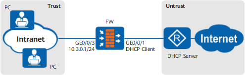
As shown in Figure Networking diagram of accessing the Internet through DHCP, the FW functions as an egress gateway and connects PCs on an intranet to the Internet. The network plan is as follows:
- The PCs on the intranet are deployed on the 10.3.0.0/24 network segment. The customer wants the FW to assign IP addresses to intranet users and implement Internet access for intranet users.
- The FW functions as a DHCP client and applies to a DHCP server (carrier device) for IPv4 and DNS addresses for Internet access of intranet users.
Configuration Roadmap
- Enable the DHCP client function on GigabitEthernet 0/0/1 of the FW to obtain IPv4 and DNS server addresses from a DHCP server.
- Configure an IPv4 address on GigabitEthernet 0/0/3 of the FW for connecting to the intranet.
- Configure GigabitEthernet 0/0/3 of the FW as a DHCP server to dynamically assign IPv4 and DNS server addresses to the intranet. Configure intranet PCs to automatically obtain IP addresses and the DNS server address.
- Configure a security policy and a NAT policy (easy-IP) on the FW.

After the firewall obtains IPv4 addresses from the DHCP server, the DHCP server sends the default route to the DHCP client. The next hop address of the default route is the carrier's device. Therefore, no extra default route is required in this networking.
Procedure
- Configure IP addresses of interfaces and add the interfaces to security zones.
- Click
 corresponding to GigabitEthernet 0/0/1 and set the parameters as follows.
Zone
untrust
Mode
Routing
IPv4
Connection Type
DHCP
- Click
- Configure the dynamic DNS resolution. Currently, the configuration cannot be performed on the web UI. Click CLI Console in the lower right corner of the page to display the CLI configuration page and configure it on the CLI.
[FW] dns resolve - Configure GigabitEthernet 0/0/3 as a DHCP server to assign IP addresses to the intranet.
- In DHCP Service List, click Add and configure the DHCP service as follows.
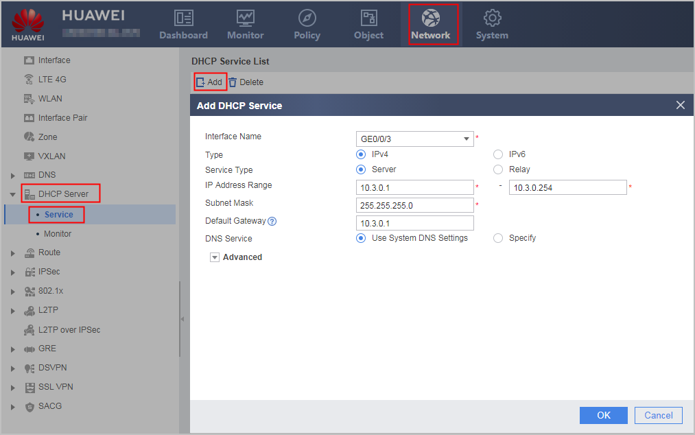
- In DHCP Service List, click Add and configure the DHCP service as follows.
- Configure security policies so that intranet PCs can access the Internet.
- Configure a NAT policy to translate private IP addresses into public IP addresses before intranet PCs access the Internet.
- Choose .
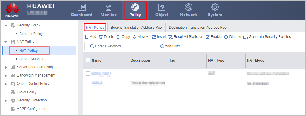
- In NAT Policy List, click Add and configure a NAT policy based on the following parameter values.
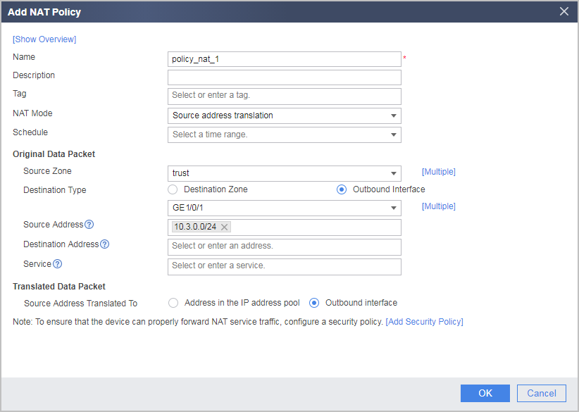
- Choose .
Verification
- Check the status of GigabitEthernet 0/0/1 (uplink).
- Choose .
- Verify that the physical status and IPv4 status of the interface are Up, the connection type is DHCP, and the interface has obtained an IPv4 address.
- Check whether the PCs on the intranet can use domain names to access the Internet. If the PCs can access the Internet, the configuration is successful. If the PCs fail to access the Internet, modify the configuration and try again.
Configuration Scripts
#
 dns resolve
 dns server unnumbered interface GigabitEthernet0/0/1
#
 dns proxy enable
#
 dhcp enable
#
 interface GigabitEthernet0/0/1
  undo shutdown
  ip address dhcp-alloc
#
 interface GigabitEthernet0/0/3
  undo shutdown
  ip address 10.3.0.1 255.255.255.0
  dhcp server mask 255.255.255.0
  dhcp select interface
  dhcp server gateway-list 10.3.0.1
  dhcp server dns-list 10.3.0.1
#
 firewall zone trust
  set priority 85
  add interface GigabitEthernet0/0/3
#
 firewall zone untrust
  set priority 5
  add interface GigabitEthernet0/0/1
#
 security-policy
 rule name sec_policy_1
  source-zone trust
  destination-zone untrust
  source-address 10.3.0.0 mask 255.255.255.0
  action permit
 rule name sec_policy_2
  source-zone trust
  destination-zone local
  source-address 10.3.0.0 mask 255.255.255.0
  service dns
  action permit
 rule name sec_policy_3
  source-zone local
  destination-zone untrust
  service dns
  action permit
#
 nat-policy
  rule name policy_nat_1
    source-zone trust
    egress-interface GigabitEthernet0/0/1
    source-address 10.3.0.0 24
    action source-nat easy-ip
#
return