CLI: Example for Configuring Multi-server Smart DNS in ISP Egress Mode
This section provides an example for configuring multi-server smart DNS in ISP egress mode.
Networking Requirements
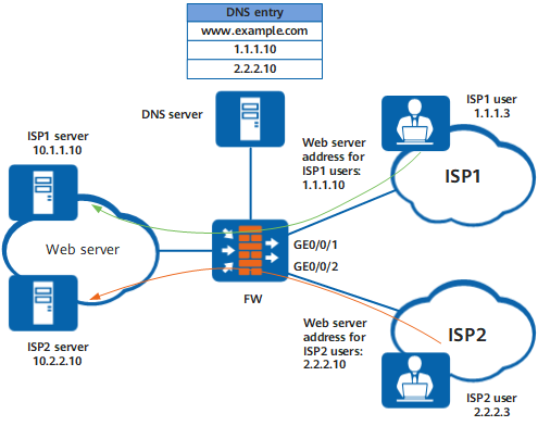
As shown in Figure 1, an enterprise deploys two web servers to provide the web service whose domain name is www.example.com. The private IP address of ISP1 server is 10.1.1.10, and the public IP address after server mapping is 1.1.1.10. The private IP address of ISP2 server is 10.2.2.10, and the public IP address after server mapping is 2.2.2.10. The DNS server of on the intranet of the enterprise has the mappings between domain name www.example.com and the two server addresses (1.1.1.10 and 2.2.2.10).
An ISP1 user who accesses www.example.com obtains ISP1 server address 1.1.1.10 and accesses ISP1 server through ISP1 network. An ISP2 user who accesses www.example.com obtains ISP2 server address 2.2.2.10 and accesses ISP2 server through ISP2 network.
Configuration Roadmap
As shown in Figure 1, ISP users usually obtain ISP server addresses 1.1.1.10 and 2.2.2.10. To enable ISP1 users to obtain ISP1 server address and ISP2 users to obtain ISP2 server address, configure smart DNS in ISP egress mode. The configuration roadmap is as follows:
Because two web servers are deployed on the intranet, configure multi-server smart DNS in ISP egress mode. Multi-server smart DNS needs to associate the ISP egresses and public ISP server addresses. For example, associate GE0/0/1 of ISP1 network with public ISP1 server address 1.1.1.10 and GE0/0/2 of ISP2 network with public ISP2 server address 2.2.2.10.
Procedure
- Enable smart DNS.
<FW> system-view
[FW] dns-smart enable
- Create a smart DNS group and configure smart DNS mappings in the group view.
- Configure the NAT server function.
- Configure the sticky load balancing function.
[FW] interface GigabitEthernet0/0/1
[FW-GigabitEthernet0/0/1] ip address 1.1.1.2 24
[FW-GigabitEthernet0/0/1] gateway 1.1.1.1
[FW-GigabitEthernet0/0/1] redirect-reverse next-hop 1.1.1.1
[FW-GigabitEthernet0/0/1] quit
[FW] interface GigabitEthernet0/0/2
[FW-GigabitEthernet0/0/2] ip address 2.2.2.2 24
[FW-GigabitEthernet0/0/2] gateway 2.2.2.1
[FW-GigabitEthernet0/0/2] redirect-reverse next-hop 2.2.2.1
[FW-GigabitEthernet0/0/2] quit
Configuration Scripts
#
 nat server isp1_server_nat global 1.1.1.10 inside 10.1.1.10 no-reverse
 nat server isp2_server_nat global 2.2.2.10 inside 10.2.2.10 no-reverse
#
 dns-smart enable
#
dns-smart group 1 type multi
 out-interface GigabitEthernet0/0/1 map 1.1.1.10
 out-interface GigabitEthernet0/0/2 map 2.2.2.10
#
interface GigabitEthernet0/0/1
 ip address 1.1.1.2 255.255.255.0
 redirect-reverse next-hop 1.1.1.1
 gateway 1.1.1.1
#
interface GigabitEthernet0/0/2
 ip address 2.2.2.2 255.255.255.0
 redirect-reverse next-hop 2.2.2.1
 gateway 2.2.2.1