CLI: Configuring Internet Users to Access Intranet Servers of Virtual Systems Through the WAN Interface of the Public System (Performing NAT in Each Virtual System)
Networking Requirements
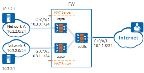
As shown in Figure 1, the device is deployed as a Layer 3 gateway between the intranet and Internet. The intranet is divided into two independent LANs: network A and network B, which are isolated from each other and have overlapping IP addresses.
User hosts on the Internet access servers on networks A and B through the shared WAN interface GE0/0/1 of the public system. In addition, a NAT Server is configured for each virtual system. User hosts on the Internet can access specific servers on networks A and B attached to the virtual systems through independent public IP addresses.
Item |
Data |
Description |
|---|---|---|
public |
WAN interface: GE0/0/1 WAN interface IP address: 10.1.1.8/24 Security zone to which the WAN interface belongs: untrust LAN interface: virtual system Virtual-if0 of the public system Security zone to which the LAN interface belongs: trust IP address of the carrier access gateway: 10.1.1.1/24 |
In this example, all intranet servers provide services for Internet users through the WAN interface of the public system. As the private IP addresses of networks A and B attached to the virtual systems overlap, you need to configure NAT Server for each virtual system. |
vsysa |
Virtual system name: vsysa WAN interface: virtual interface Virtual-if1 of vsysa Security zone to which the WAN interface belongs: untrust LAN interface: GE0/0/2 LAN interface IP address: 10.3.0.1/24 Private IP address range: 10.3.2.0/24 Security zone to which the LAN interface belongs: trust Private IP address and port of the intranet server: 10.3.2.1:80 Public IP address and port after NAT of the intranet server for Internet users: 10.10.1.1:8080 |
In this example, you can configure a NAT Server to enable user hosts on the Internet to access the server at 10.3.2.1 on network A through the IP address 10.10.1.1. |
vsysb |
Virtual system name: vsysb WAN interface: virtual interface Virtual-if2 of vsysb Security zone to which the WAN interface belongs: untrust LAN interface: GE0/0/3 LAN interface IP address: 10.3.1.1/24 Private IP address range: 10.3.2.0/24 Security zone to which the LAN interface belongs: trust Private IP address and port of the intranet server: 10.3.2.1:80 Public IP address and port after NAT of the intranet server for Internet users: 10.10.1.2:8080 |
In this example, you can configure a NAT Server to enable user hosts on the Internet to access the server at 10.3.2.1 on network B through the IP address 10.10.1.2. |
Resource class |
Resource class name: r1 Guaranteed number of IPv4 sessions: 10000 Maximum number of IPv4 sessions: 50000 Guaranteed number of policies: 300 Guaranteed total bandwidth: 20 Mbit/s |
In this example, networks A and B have similar service resource usage requirements and therefore are allocated the same virtual system resources. |
Configuration Roadmap
- Enable the virtual system function.
- Configure resource classes based on service requirements, create virtual systems vsysa and vsysb in the public system, and allocate resources to the virtual systems.
- Configure interfaces for the public system, vsysa, and vsysb, and add the interfaces to security zones.
- Configure routes in the public system, vsysa, and vsysb to divert traffic from the Internet to networks A and B.
- Configure security policies in the public system, vsysa, and vsysb based on service requirements to permit traffic from user hosts on the Internet to servers on networks A and B.
- Configure a NAT Server in both vsysa and vsysb to enable user hosts on the Internet to access specific servers on networks A and B attached to the virtual systems through independent public IP addresses.
Procedure
- Enable the virtual system function.
<FW> system-view
[FW] vsys enable
- Configure a resource class.
[FW] resource-class r1
[FW-resource-class-r1] resource-item-limit session reserved-number 10000 maximum 50000
[FW-resource-class-r1] resource-item-limit policy reserved-number 300
[FW-resource-class-r1] resource-item-limit bandwidth 20 entire
[FW-resource-class-r1] quit
- Create virtual systems and allocate resources to them.
# Create virtual system vsysa and allocate resources to it.
[FW] vsys name vsysa
[FW-vsys-vsysa] assign resource-class r1
[FW-vsys-vsysa] assign interface GigabitEthernet 0/0/2
[FW-vsys-vsysa] assign global-ip 10.10.1.1 10.10.1.1 exclusive
[FW-vsys-vsysa] quit
# Create virtual system vsysb and allocate resources to it.
[FW] vsys name vsysb
[FW-vsys-vsysb] assign resource-class r1
[FW-vsys-vsysb] assign interface GigabitEthernet 0/0/3
[FW-vsys-vsysb] assign global-ip 10.10.1.2 10.10.1.2 exclusive
[FW-vsys-vsysb] quit
- Configure interfaces for the public system and add the interfaces to security zones.
[FW] interface GigabitEthernet 0/0/1
[FW-GigabitEthernet0/0/1] ip address 10.1.1.8 24
[FW-GigabitEthernet0/0/1] quit
[FW] interface Virtual-if 0
[FW-Virtual-if0] ip address 172.16.0.1 24
[FW-Virtual-if0] quit
[FW] firewall zone trust
[FW-zone-trust] add interface Virtual-if 0
[FW-zone-trust] quit
[FW] firewall zone untrust
[FW-zone-untrust] add interface GigabitEthernet 0/0/1
[FW-zone-untrust] quit
- Configure routes in the public system.
# Configure a route from the public system to the Internet. 10.1.1.1 is the next-hop address of the route from the public system to the Internet.
[FW] ip route-static 0.0.0.0 0.0.0.0 10.1.1.1# Configure a route from the public system to vsysa to divert traffic from the Internet to network A.
[FW] ip route-static 10.10.1.1 32 vpn-instance vsysa# Configure a route from the public system to vsysb to divert traffic from the Internet to network A.
[FW] ip route-static 10.10.1.2 32 vpn-instance vsysb - Configure a security policy in the public system to permit traffic from user hosts on the Internet to servers on networks A and B.
[FW] security-policy
[FW-policy-security] rule name untrust_to_trust
[FW-policy-security-rule-untrust_to_trust] source-zone untrust
[FW-policy-security-rule-untrust_to_trust] destination-zone trust
[FW-policy-security-rule-untrust_to_trust] destination-address 10.10.1.1 32
[FW-policy-security-rule-untrust_to_trust] destination-address 10.10.1.2 32
[FW-policy-security-rule-untrust_to_trust] action permit
[FW-policy-security-rule-untrust_to_trust] quit
[FW-policy-security] quit
- Switch to the system view of vsysa.
[FW] switch vsys vsysa
<FW-vsysa> system-view
- Configure interfaces for vsysa and add the interfaces to security zones.
[FW-vsysa] interface GigabitEthernet 0/0/2
[FW-vsysa-GigabitEthernet0/0/2 ip address 10.3.0.1 24
[FW-vsysa-GigabitEthernet0/0/2] quit
[FW-vsysa] interface Virtual-if 1
[FW-vsysa-Virtual-if1] ip address 172.16.1.1 24
[FW-vsysa-Virtual-if1] quit
[FW-vsysa] firewall zone trust
[FW-vsysa-zone-trust] add interface GigabitEthernet 0/0/2
[FW-vsysa-zone-trust] quit
[FW-vsysa] firewall zone untrust
[FW-vsysa-zone-untrust] add interface Virtual-if 1
[FW-vsysa-zone-untrust] quit
- Configure a route from vsysa to network A. 10.3.0.254 is the next-hop address of the route from vsysa to network A.
[FW-vsysa] ip route-static 10.3.2.0 255.255.255.0 10.3.0.254 - Configure a security policy in vsysa to permit traffic from user hosts on the Internet to servers on network A.
[FW-vsysa] security-policy
[FW-vsysa-policy-security] rule name to_network_allow
[FW-vsysa-policy-security-rule-to_network_allow] source-zone untrust
[FW-vsysa-policy-security-rule-to_network_allow] destination-zone trust
[FW-vsysa-policy-security-rule-to_network_allow] destination-address 10.3.2.1 32
[FW-vsysa-policy-security-rule-to_network_allow] action permit
[FW-vsysa-policy-security-rule-to_network_allow] quit
[FW-vsysa-policy-security] quit
- Configure a NAT Server in vsysa to enable user hosts on the Internet to access servers on network A through a public IP address.
[FW-vsysa] nat server to_public_server protocol tcp global 10.10.1.1 8080 inside 10.3.2.1 www no-reverse - Switch to the system view of vsysb.
[FW-vsysa] quit
<FW-vsysa> quit
[FW] switch vsys vsysb
<FW-vsysb> system-view
- Configure interfaces for vsysb and add the interfaces to security zones.
[FW-vsysb] interface GigabitEthernet 0/0/3
[FW-vsysb-GigabitEthernet0/0/3] ip address 10.3.1.1 24
[FW-vsysb-GigabitEthernet0/0/3] quit
[FW-vsysb] interface Virtual-if 2
[FW-vsysb-Virtual-if2] ip address 172.16.2.1 24
[FW-vsysb-Virtual-if2] quit
[FW-vsysb] firewall zone trust
[FW-vsysb-zone-trust] add interface GigabitEthernet 0/0/3
[FW-vsysb-zone-trust] quit
[FW-vsysb] firewall zone untrust
[FW-vsysb-zone-untrust] add interface Virtual-if 2
[FW-vsysb-zone-untrust] quit
- Configure a route from vsysb to network B. 10.3.1.254 is the next-hop address of the route from vsysb to network B.
[FW-vsysb] ip route-static 10.3.2.0 255.255.255.0 10.3.1.254 - Configure a security policy in vsysb to permit traffic from user hosts on the Internet to servers on network B.
[FW-vsysb] security-policy
[FW-vsysb-policy-security] rule name to_network_allow
[FW-vsysb-policy-security-rule-to_network_allow] source-zone untrust
[FW-vsysb-policy-security-rule-to_network_allow] destination-zone trust
[FW-vsysb-policy-security-rule-to_network_allow] destination-address 10.3.2.1 32
[FW-vsysb-policy-security-rule-to_network_allow] action permit
[FW-vsysb-policy-security-rule-to_network_allow] quit
[FW-vsysb-policy-security] quit
- Configure a NAT Server in vsysb to enable user hosts on the Internet to access servers on network B through a public IP address.
[FW-vsysb] nat server to_public_server protocol tcp global 10.10.1.2 8080 inside 10.3.2.1 www no-reverse
Verifying the Configuration
- User hosts on the Internet can access the web server at 10.3.0.2 on network A through http://10.10.1.1:8080.
- User hosts on the Internet can access the web server at 10.3.1.2 on network B through http://10.10.1.2:8080.
Configuration Scripts
- Public system
# sysname FW # vsys enable # resource-class r1 resource-item-limit session reserved-number 10000 maximum 50000 resource-item-limit policy reserved-number 300 resource-item-limit bandwidth 20 entire # vsys name vsysa 1 assign resource-class r1 assign interface GigabitEthernet0/0/2 assign global-ip 10.10.1.1 10.10.1.1 exclusive # vsys name vsysb 2 assign resource-class r1 assign interface GigabitEthernet0/0/3 assign global-ip 10.10.1.2 10.10.1.2 exclusive # interface GigabitEthernet0/0/1 undo shutdown ip address 10.1.1.8 24 # interface Virtual-if 0 ip address 172.16.0.1 255.255.255.0 # firewall zone trust set priority 85 add interface Virtual-if0 # firewall zone untrust set priority 5 add interface GigabitEthernet0/0/1 # ip route-static 0.0.0.0 0.0.0.0 10.1.1.1 ip route-static 10.10.1.1 32 vpn-instance vsysa ip route-static 10.10.1.2 32 vpn-instance vsysb # security-policy rule name untrust_to_trust source-zone untrust destination-zone trust destination-address 10.10.1.1 mask 255.255.255.255 destination-address 10.10.1.2 mask 255.255.255.255 action permit # return - Virtual system (vsysa)
#
interface GigabitEthernet0/0/2
 ip address 10.3.0.1 255.255.255.0
#
interface Virtual-if 1
 ip address 172.16.1.1 255.255.255.0
#
firewall zone trust
 set priority 85
 add interface GigabitEthernet0/0/2
#
firewall zone untrust
 set priority 5
 add interface Virtual-if1
#
 ip route-static 10.3.2.0 255.255.255.0 10.3.0.254
#
security-policy
 rule name to_network_allow
  source-zone untrust
  destination-zone trust
  destination-address 10.3.2.1 mask 255.255.255.255
  action permit
#
 nat server to_public_server protocol tcp global 10.10.1.1 8080 inside 10.3.2.1 www no-reverse
#
return
- Virtual system (vsysb)
#
interface GigabitEthernet0/0/3
 ip address 10.3.1.1 255.255.255.0
#
interface Virtual-if 2
 ip address 172.16.2.1 255.255.255.0
#
firewall zone trust
 set priority 85
 add interface GigabitEthernet0/0/3
#
firewall zone untrust
 set priority 5
 add interface Virtual-if2
#
 ip route-static 10.3.2.0 255.255.255.0 10.3.1.254
#
security-policy
 rule name to_network_allow
  source-zone untrust
  destination-zone trust
  destination-address 10.3.2.1 mask 255.255.255.255
  action permit
#
 nat server to_public_server protocol tcp global 10.10.1.2 8080 inside 10.3.2.1 www no-reverse
#
return