CLI Example: Configuring Non-Shortcut Scenario of DSVPN (OSPF)
Networking Requirements
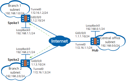
A small enterprise has a central office (Hub) and two branches (Spoke1 and Spoke2) which are located in different areas. The networks of the central office and branches frequently change. The Spokes use dynamic addresses to connect to the public network. Open Shortest Path First (OSPF) is used on the enterprise network.
The enterprise wants to establish a VPN between the Spokes.
Configuration Roadmap
Because a Spoke uses a dynamic address to connect to the public network, it does not know the public IP address of the other Spoke. DSVPN is implemented to establish a VPN between the Spokes.
Non-Shortcut Scenario of DSVPN is implemented because the enterprise has a small number of branches.
The networks of the central office and branches frequently change. OSPF is deployed to realize communication between the Hub and Spokes and to simplify maintenance.
Procedure
- Assign an IP address to each interface.
Configure IP addresses for the interfaces of each FW.
# Configure IP addresses for interfaces of Hub.
<sysname> system-view
[sysname] sysname Hub
[Hub] interface GigabitEthernet 0/0/0
[Hub-GigabitEthernet0/0/0] ip address 1.1.1.10 255.255.255.0
[Hub-GigabitEthernet0/0/0] quit
[Hub] interface tunnel 0
[Hub-Tunnel0] ip address 172.16.1.1 255.255.255.0
[Hub-Tunnel0] quit
[Hub] interface loopback 0
[Hub-LoopBack0] ip address 192.168.0.1 255.255.255.0
[Hub-LoopBack0] quit
Configure IP addresses for interfaces of the Spoke1 and Spoke2 as shown in Figure 1. The specific configuration is not mentioned here.
- Configure security zones and security policies.
# Configure security zones on each device. The configuration commands are the same, and the Hub is used as an example.
[Hub] firewall zone untrust
[Hub-zone-untrust] add interface GigabitEthernet 0/0/0
[Hub-zone-untrust] add interface tunnel 0
[Hub-zone-untrust] quit
# Configure security policies on each device. The configuration commands are the same, and the Hub is used as an example.
In this example, loopback interfaces in the Local zone are used to simulate subnet users. Therefore, the interzone policy between the Local zone and security zone where the tunnel interface resides needs to be configured (in this example, policy rule1 is configured). Actually, the interzone policy between the security zones where subnets reside needs to be configured. For example, if the subnet of the enterprise resides in the Trust zone, configure the interzone policy between the Trust zone and security zone where the tunnel interface resides.
[Hub] security-policy
[Hub-policy-security] rule name rule1
[Hub-policy-security-rule-rule1] source-zone untrust local
[Hub-policy-security-rule-rule1] destination-zone untrust local
[Hub-policy-security-rule-rule1] sourse-address 192.168.0.0 mask 255.255.0.0
[Hub-policy-security-rule-rule1] action permit
[Hub-policy-security-rule-rule1] quit
[Hub-policy-security] rule name rule2
[Hub-policy-security-rule-rule2] source-zone untrust local
[Hub-policy-security-rule-rule2] destination-zone untrust local
[Hub-policy-security-rule-rule2] service gre ospf
[Hub-policy-security-rule-rule2] action permit
[Hub-policy-security-rule-rule2] quit
[Hub-policy-security] quit
- Configure routes between the FWs.
Configure OSPF on each FW to provide reachable routes to the public network.
# Configure OSPF on Hub.
[Hub] ospf 2 router-id 1.1.1.10
[Hub-ospf-2] area 0.0.0.1
[Hub-ospf-2-area-0.0.0.1] network 1.1.1.0 0.0.0.255
[Hub-ospf-2-area-0.0.0.1] quit
[Hub-ospf-2] quit
# Configure OSPF on Spoke1.
[Spoke1] ospf 2 router-id 1.1.2.10
[Spoke1-ospf-2] area 0.0.0.1
[Spoke1-ospf-2-area-0.0.0.1] network 1.1.2.0 0.0.0.255
[Spoke1-ospf-2-area-0.0.0.1] quit
[Spoke1-ospf-2] quit
# Configure OSPF on Spoke2.
[Spoke2] ospf 2 router-id 1.1.3.10
[Spoke2-ospf-2] area 0.0.0.1
[Spoke2-ospf-2-area-0.0.0.1] network 1.1.3.0 0.0.0.255
[Spoke2-ospf-2-area-0.0.0.1] quit
[Spoke2-ospf-2] quit
- Configure the basic OSPF functions.
# Configure Hub.
[Hub] ospf 1 router-id 172.16.1.1
[Hub-ospf-1] area 0.0.0.0
[Hub-ospf-1-area-0.0.0.0] network 172.16.1.0 0.0.0.255
[Hub-ospf-1-area-0.0.0.0] network 192.168.0.0 0.0.0.255
[Hub-ospf-1-area-0.0.0.0] quit
[Hub-ospf-1] quit
# Configure Spoke1.
[Spoke1] ospf 1 router-id 172.16.1.2
[Spoke1-ospf-1] area 0.0.0.0
[Spoke1-ospf-1-area-0.0.0.0] network 172.16.1.0 0.0.0.255
[Spoke1-ospf-1-area-0.0.0.0] network 192.168.1.0 0.0.0.255
[Spoke1-ospf-1-area-0.0.0.0] quit
[Spoke1-ospf-1] quit
# Configure Spoke2.
[Spoke2] ospf 1 router-id 172.16.1.3
[Spoke2-ospf-1] area 0.0.0.0
[Spoke2-ospf-1-area-0.0.0.0] network 172.16.1.0 0.0.0.255
[Spoke2-ospf-1-area-0.0.0.0] network 192.168.2.0 0.0.0.255
[Spoke2-ospf-1-area-0.0.0.0] quit
[Spoke2-ospf-1] quit

The OSPF configuration on a Spoke subnet is given as an example. Perform the same configuration on other Spoke subnets.
When the subnet of a branch changes, you only need to configure the dynamic routing policy on the local device.
- Configure tunnel interfaces.
Set the OSPF network type to broadcast on Hub and Spokes to allow Spokes to learn routes from each other. Configure static NHRP mapping entries of Hub on Spoke1 and Spoke2.
# Configure a tunnel interface and OSPF on Hub.[Hub] interface tunnel 0 [Hub-Tunnel0] tunnel-protocol gre p2mp [Hub-Tunnel0] source GigabitEthernet 0/0/0 [Hub-Tunnel0] nhrp entry multicast dynamic [Hub-Tunnel0] ospf network-type broadcast [Hub-Tunnel0] quit# On Spoke1, configure a tunnel interface, OSPF, and a static NHRP mapping entry of Hub.[Spoke1] interface tunnel 0 [Spoke1-Tunnel0] tunnel-protocol gre p2mp [Spoke1-Tunnel0] source GigabitEthernet 0/0/0 [Spoke1-Tunnel0] nhrp entry 172.16.1.1 1.1.1.10 register [Spoke1-Tunnel0] ospf network-type broadcast [Spoke1-Tunnel0] ospf dr-priority 0 [Spoke1-Tunnel0] quit# On Spoke2, configure a tunnel interface, OSPF, and a static NHRP mapping entry of Hub.[Spoke2] interface tunnel 0 [Spoke2-Tunnel0] tunnel-protocol gre p2mp [Spoke2-Tunnel0] source GigabitEthernet 0/0/0 [Spoke2-Tunnel0] nhrp entry 172.16.1.1 1.1.1.10 register [Spoke2-Tunnel0] ospf network-type broadcast [Spoke2-Tunnel0] ospf dr-priority 0 [Spoke2-Tunnel0] quit - Verify the configuration.
After the preceding configurations are complete, check the NHRP mapping entries of Spoke1 and Spoke2.
# Run the display nhrp peer all command on Spoke1. The command output is as follows:
[Spoke1] display nhrp peer all
-------------------------------------------------------------------------------
Protocol-addr   Mask  NBMA-addr       NextHop-addr    Type         Flag
-------------------------------------------------------------------------------
172.16.1.1      32    1.1.1.10        172.16.1.1       hub          up
-------------------------------------------------------------------------------
Tunnel interface: Tunnel0
Created time    : 00:10:58
Expire time     : -- HostName        : Hub HostEsn         : 210235G7G610F1000002

Number of nhrp peers: 1
# Run the display nhrp peer all command on Spoke2. The command output is as follows:
[Spoke2] display nhrp peer all
-------------------------------------------------------------------------------
Protocol-addr   Mask  NBMA-addr       NextHop-addr    Type         Flag
-------------------------------------------------------------------------------
172.16.1.1      32    1.1.1.10        172.16.1.1       hub          up
-------------------------------------------------------------------------------
Tunnel interface: Tunnel0
Created time    : 00:07:55
Expire time     : -- HostName        : Hub HostEsn         : 210235G7G610F1000002

Number of nhrp peers: 1
If you run the display nhrp peer all command on Spoke1 and Spoke2, you can view only the static NHRP mapping entry of Hub.
On Hub, check the NHRP mapping entries of Spoke1 and Spoke2.
# Run the display nhrp peer all command on Hub. The command output is as follows:
[Hub] display nhrp peer all
-------------------------------------------------------------------------------
Protocol-addr   Mask  NBMA-addr       NextHop-addr    Type         Flag
-------------------------------------------------------------------------------
172.16.1.2      32    1.1.2.10        172.16.1.2      registered   up|unique
-------------------------------------------------------------------------------
Tunnel interface: Tunnel0
Created time    : 00:02:02
Expire time     : 01:57:58 HostName        : Spoke1 HostEsn         : 210235G7G610F1000013
-------------------------------------------------------------------------------
Protocol-addr   Mask  NBMA-addr       NextHop-addr    Type         Flag
-------------------------------------------------------------------------------
172.16.1.3      32    1.1.3.10        172.16.1.3      registered   up|unique
-------------------------------------------------------------------------------
Tunnel interface: Tunnel0
Created time    : 00:01:53
Expire time     : 01:59:35 HostName        : Spoke2 HostEsn         : 210235G7G610F3000017

Number of nhrp peers: 2
- Run the ping command to check the configuration result.
To use the ping command for link detection, run the service-manage ping permit command in the interface view to set the ping service of all firewall interfaces on the link to permit.
Ping 192.168.2.1 on Spoke1. You can see that Spoke1 and Spoke2 have learned dynamic NHRP mapping entries from each other.
# Run the ping -a 192.168.1.1 192.168.2.1 command on Spoke1. The command output is as follows:
[Spoke1] ping -a 192.168.1.1 192.168.2.1
  PING 192.168.2.1: 56  data bytes, press CTRL_C to break
    Reply from 192.168.2.1: bytes=56 Sequence=1 ttl=254 time=2 ms
    Reply from 192.168.2.1: bytes=56 Sequence=2 ttl=255 time=2 ms
    Reply from 192.168.2.1: bytes=56 Sequence=3 ttl=255 time=2 ms
    Reply from 192.168.2.1: bytes=56 Sequence=4 ttl=255 time=2 ms
    Reply from 192.168.2.1: bytes=56 Sequence=5 ttl=255 time=2 ms

  --- 192.168.2.1 ping statistics ---
    5 packet(s) transmitted
    5 packet(s) received
    0.00% packet loss
    round-trip min/avg/max = 2/2/2 ms
# Run the display nhrp peer all command on Spoke1. The command output is as follows:
[Spoke1] display nhrp peer all
-------------------------------------------------------------------------------
Protocol-addr   Mask  NBMA-addr       NextHop-addr    Type            Flag
-------------------------------------------------------------------------------
172.16.1.1      32    1.1.1.10        172.16.1.1      hub              up
-------------------------------------------------------------------------------
Tunnel interface: Tunnel0
Created time    : 00:46:35
Expire time     : -- HostName        : Hub HostEsn         : 210235G7G610F1000002
-------------------------------------------------------------------------------
Protocol-addr   Mask  NBMA-addr       NextHop-addr    Type            Flag
-------------------------------------------------------------------------------
172.16.1.3      32    1.1.3.10        172.16.1.3      remote          up
-------------------------------------------------------------------------------
Tunnel interface: Tunnel0
Created time    : 00:00:28
Expire time     : 01:59:32 HostName        : Spoke2 HostEsn         : 210235G7G610F3000017
-------------------------------------------------------------------------------
Protocol-addr   Mask  NBMA-addr       NextHop-addr    Type            Flag
-------------------------------------------------------------------------------
172.16.1.2      32    1.1.2.10        172.16.1.2      local           up
-------------------------------------------------------------------------------
Tunnel interface: Tunnel0
Created time    : 00:00:28
Expire time     : 01:59:32 HostName        : Spoke1 HostEsn         : 210235G7G610F1000013

Number of nhrp peers: 3
# Run the display nhrp peer all command on Spoke2. The command output is as follows:
[Spoke2] display nhrp peer all
-------------------------------------------------------------------------------
Protocol-addr   Mask  NBMA-addr       NextHop-addr    Type         Flag
-------------------------------------------------------------------------------
172.16.1.1      32    1.1.1.10        172.16.1.1      hub           up
-------------------------------------------------------------------------------
Tunnel interface: Tunnel0
Created time    : 00:43:32
Expire time     : -- HostName        : Hub HostEsn         : 210235G7G610F1000002
-------------------------------------------------------------------------------
Protocol-addr   Mask  NBMA-addr       NextHop-addr    Type         Flag
-------------------------------------------------------------------------------
172.16.1.2      32    1.1.2.10        172.16.1.2      remote       up
-------------------------------------------------------------------------------
Tunnel interface: Tunnel0
Created time    : 00:00:47
Expire time     : 01:59:13 HostName        : Spoke1 HostEsn         : 210235G7G610F1000013
-------------------------------------------------------------------------------
Protocol-addr   Mask  NBMA-addr       NextHop-addr    Type         Flag
-------------------------------------------------------------------------------
172.16.1.3      32    1.1.3.10        172.16.1.3      local        up
-------------------------------------------------------------------------------
Tunnel interface: Tunnel0
Created time    : 00:00:47
Expire time     : 01:59:13 HostName        : Spoke2 HostEsn         : 210235G7G610F3000017

Number of nhrp peers: 3
Configuration Files
-
#
sysname Hub
#
interface GigabitEthernet0/0/0
 ip address 1.1.1.10 255.255.255.0
#
interface LoopBack0
 ip address 192.168.0.1 255.255.255.0
#
interface Tunnel0
 ip address 172.16.1.1 255.255.255.0
 tunnel-protocol gre p2mp
 source GigabitEthernet0/0/0
 ospf network-type broadcast
 nhrp entry multicast dynamic
#
ospf 1 router-id 172.16.1.1
 area 0.0.0.0
  network 172.16.1.0 0.0.0.255
  network 192.168.0.0 0.0.0.255
#
ospf 2 router-id 1.1.1.10
 area 0.0.0.1
  network 1.1.1.0 0.0.0.255
#
firewall zone untrust
 add interface GigabitEthernet0/0/0
 add interface Tunnel0
#
 security-policy
  rule name rule1
   source-zone local
   source-zone untrust
   destination-zone local
   destination-zone untrust
   source-address 192.168.0.0 mask 255.255.0.0
   action permit
  rule name rule2
   source-zone local
   source-zone untrust
   destination-zone local
   destination-zone untrust
   service gre
   service ospf
   action permit
#
return
-
#
sysname Spoke1
#
interface GigabitEthernet0/0/0
 ip address 1.1.2.10 255.255.255.0
#
interface LoopBack0
 ip address 192.168.1.1 255.255.255.0
#
interface Tunnel0
 ip address 172.16.1.2 255.255.255.0
 tunnel-protocol gre p2mp
 source GigabitEthernet0/0/0
 ospf network-type broadcast
 ospf dr-priority 0
 nhrp entry 172.16.1.1 1.1.1.10 register
#
ospf 1 router-id 172.16.1.2
 area 0.0.0.0
  network 172.16.1.0 0.0.0.255
  network 192.168.1.0 0.0.0.255
#
ospf 2 router-id 1.1.2.10
 area 0.0.0.1
  network 1.1.2.0 0.0.0.255
#
firewall zone untrust
 add interface GigabitEthernet0/0/0
 add interface Tunnel0
#
 security-policy
  rule name rule1
   source-zone local
   source-zone untrust
   destination-zone local
   destination-zone untrust
   source-address 192.168.0.0 mask 255.255.0.0
   action permit
  rule name rule2
   source-zone local
   source-zone untrust
   destination-zone local
   destination-zone untrust
   service gre
   service ospf
   action permit
#
return
-
#
sysname Spoke2
#
interface GigabitEthernet0/0/0
 ip address 1.1.3.10 255.255.255.0
#
interface LoopBack0
 ip address 192.168.2.1 255.255.255.0
#
interface Tunnel0
 ip address 172.16.1.3 255.255.255.0
 tunnel-protocol gre p2mp
 source GigabitEthernet0/0/0
 ospf network-type broadcast
 ospf dr-priority 0
 nhrp entry 172.16.1.1 1.1.1.10 register
#
ospf 1 router-id 172.16.1.3
 area 0.0.0.0
  network 172.16.1.0 0.0.0.255
  network 192.168.2.0 0.0.0.255
#
ospf 2 router-id 1.1.3.10
 area 0.0.0.1
  network 1.1.3.0 0.0.0.255
#
firewall zone untrust
 add interface GigabitEthernet0/0/0
 add interface Tunnel0
#
 security-policy
  rule name rule1
   source-zone local
   source-zone untrust
   destination-zone local
   destination-zone untrust
   source-address 192.168.0.0 mask 255.255.0.0
   action permit
  rule name rule2
   source-zone local
   source-zone untrust
   destination-zone local
   destination-zone untrust
   service gre
   service ospf
   action permit
#
return