Mounting a Device in a Cabinet
Install the USG6515E, USG6525E, USG6550E, USG6555E, USG6560E, USG6565E, USG6575E-B, USG6580E, USG6585E, USG6605E-B, USG6610E, USG6615E, USG6620E, USG6625E, USG6630E, USG6635E, USG6650E, USG6655E to the cabinet through the expandable rear mounting ears or adjustable guide rails.
Precautions
Before installing the USG, check the following items:
- Before unpacking the carton, ensure that the packing carton is intact and not damaged or soaked. Stop unpacking if the USG is rusted or soggy. Then, investigate causes and contact the supplier.
- The cabinet is stable.
- Before installing the expandable rear mounting ears or adjustable guide rails on the USG6515E, USG6525E, USG6550E, USG6555E, USG6560E, USG6565E, USG6575E-B, USG6580E, USG6585E, USG6605E-B, USG6610E, USG6615E, USG6620E, USG6625E, USG6630E, USG6635E, USG6650E, USG6655E, adjust the distance between the front and rear angle gauges (rack mounting rails/vertical columns) to satisfy the installation requirements. The specific scope of application is as follows:
Table 1 Expandable rear mounting ears and adjustable guide rails Distance Between the Front and Rear Mounting Bars and Cabinet Type
Expandable Rear Mounting Ears and Adjustable Guide Rails
Expandable rear mounting ears (BOM number: 21240492)
- Distance between the front and rear mounting bars: 310 mm to 538 mm
- Cabinet depth: 600 mm to 800 mm
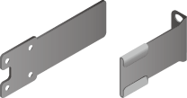
Expandable rear mounting ears (BOM number: 21240537)
- Distance between the front and rear mounting bars: 638 mm to 835 mm
- Cabinet depth: 1000 mm to 1200 mm
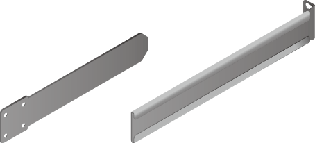
Adjustable guide rails (BOM number: 21242247)
- Distance between the front and rear mounting bars: 370 mm to 585 mm
- Cabinet depth: 600 mm to 800 mm
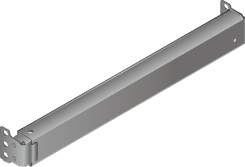
Adjustable guide rails (BOM number: 21242246)
- Distance between the front and rear mounting bars: 500 mm to 850 mm
- Cabinet depth: 1000 mm to 1200 mm
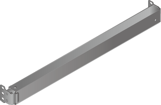
- The position for the USG in the cabinet is well arranged. Ensure that the USG is 1 U of clearance from any devices above and below and 150 mm of clearance from any devices on the right or left.
- The USG to be installed is staged near the cabinet for convenience.
- In the front view, the air flow of the USG is front to rear. If the USG and a device whose air flow is rear to front must be mounted in the same cabinet, maintain certain spacing between them to prevent hot air recirculation.
You can place either end of the USG chassis towards the front door of the cabinet. In this manual, the front panel of the USG is towards the front door of the cabinet.

The method of installing expandable rear mounting ears (BOM number: 21240492) is the same as that of installing expandable rear mounting ears (BOM number: 21240537). The following uses the expandable rear mounting ears (BOM number: 21240492) as examples.
Tools and Accessories
- Phillips screwdriver
- Floating nuts and matching screws
- Floating mounting bar
- Front mounting ears and corresponding screws
- Expandable rear mounting ears and corresponding screws (purchased separately, BOM numbers: 21240492 and 21240537)
- Adjustable guide rails and matching screws (purchased separately, BOM numbers: 21242247 and 21242246)
Procedure
- Install mounting ears on the chassis.
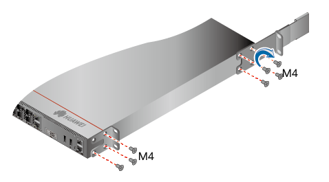
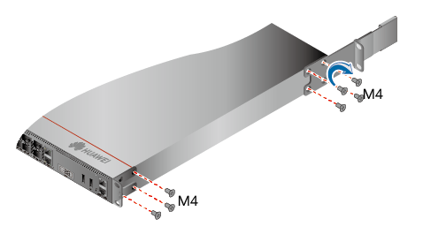
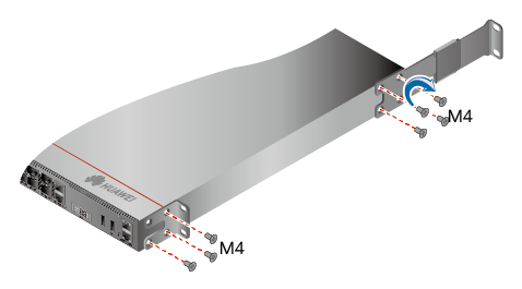
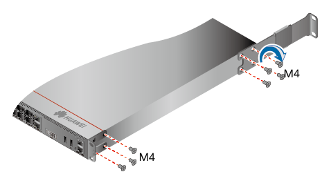
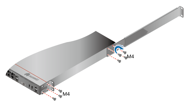
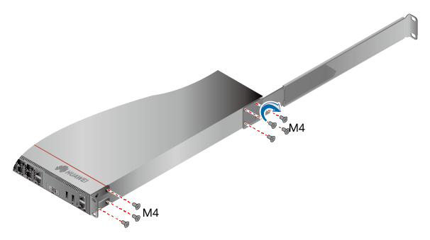
Use a Phillips screwdriver to fix the mounting ears to both sides of the chassis with M4 screws. The maximum torque is 1.4 N m. For details about how to install the mounting ears, see the installation methods in Table 2.
- The front mounting brackets, rear mounting brackets, and rear mounting bracket guide rails must be installed on both sides of the USG. Table 2 shows the installation on one side. Install them on the other side in the same way.
- To ensure sufficient cabling space, reserve at least 130 mm of vertical distance from the USG's port side to the interior side of the cabinet door.
- After the installation is complete, the rear mounting brackets and rear mounting bracket guide rails will not block cables routed from the ports or touch the cabinet door.
Table 2 Installation of front and rear mounting ears Distance Between Front and Rear Mounting Rails
Installation of Front Mounting Brackets, Rear Mounting Brackets, and Rear Mounting Bracket Guide Rails
310 mm to 351 mm
369 mm to 410 mm
438 mm to 479 mm
497 mm to 538 mm
638 mm to 696 mm
697 mm to 835 mm
- Install floating nuts and cabinet guide rails.
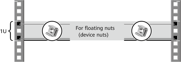
- Determine the positions for installing the guide rails and floating nuts, as shown in Figure 1.

Install the two guide rails at the same height to ensure that the device is level.
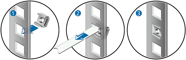
- Install the floating nuts that match M6 screws at the positions marked in Figure 1. Figure 2 illustrates how to install a floating nut.
Install guide rails in the correct direction. Identify the left and right guide rails, and the front and rear ends of each guide rail.
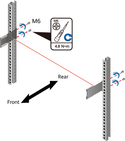
Fix expandable rear mounting ears and adjustable guide rails (at the positions marked in Figure 1) to the left and right of the cabinet with M6 screws, as shown in Figure 3.
- (Optional) Install adjustable guide rails (BOM numbers: 21242247 and 21242246). For details, see the installation guide delivered with the adjustable guide rails.
- Determine the positions for installing the guide rails and floating nuts, as shown in Figure 1.
- Mount the USG in the cabinet.
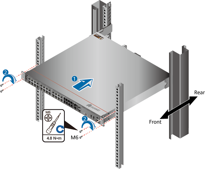
- Use M6 screws to fix the mounting ears of the USG to the mounting rack, as shown in Figure 4.