Ethernet Cable
Connection
The Ethernet cable, also called the network cable, is used for carrying signals on Gigabit networks or networks with a lower packet rate.
Ethernet cables are classified into straight-through and crossover cables according to the wiring scheme used at the two ends of the cables. The interfaces of the USG can dynamically adapt to straight-through cables and crossover cables.

Straight-through cable
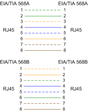
The straight-through cable is also called the standard cable. Both ends of the cable use wiring scheme EIA/TIA T568A or EIA/TIA T568B. You are advised to use wiring scheme EIA/TIA T568B when you make straight-through cables. Figure 1 shows the detail.You can use straight-through cables to connect:- A switch or hub with an USG6000E
- Computers (including servers and workstations) with a switch or hub
Crossover cable
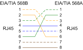
The crossover cable uses wiring scheme EIA/TIA T568A for one end and EIA/TIA T568B for the other, as shown in Figure 2.You can use the crossover cables to connect:Two USG6000Es
An USG6000E and a computer
- Two hubs
- A switch and hubs
- Two switches
- Two computers
Appearance and Structure
Network cables are classified into shielded and unshielded ones based on whether the twisted pair and RJ45 connector are shielded, as shown in Figure 3 and Figure 4.
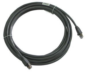
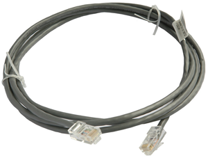

The figure is for reference only.
An Ethernet cable consists of twisted pairs and RJ45 connectors, as shown in Figure 5.

Name |
Description |
|---|---|
RJ45 |
RJ45 connector |
Cable |
Category 5 or higher twisted pair network cable |
PIN1 to PIN8 |
8 pins. Each pin has an ID ranging from 1 to 8. |
Pin Assignments
The twisted pair network cable has eight wires. The connection between wires and RJ45 connector pins complies with wiring scheme EIA/TIA 568A or EIA/TIA 568B, as shown in Figure 6.
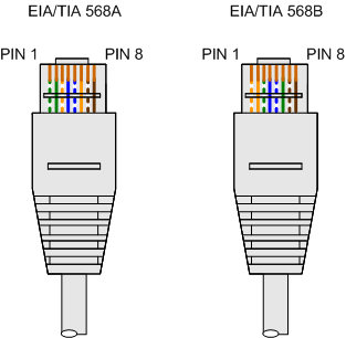
EIA/TIA 568A |
EIA/TIA 568B |
||
|---|---|---|---|
PINa |
Wireb |
PIN |
Wire |
1 |
Green/White |
1 |
Orange/White |
2 |
Green |
2 |
Orange |
3 |
Orange/White |
3 |
Green/White |
4 |
Blue |
4 |
Blue |
5 |
Blue/White |
5 |
Blue/White |
6 |
Orange |
6 |
Green |
7 |
Brown/White |
7 |
Brown/White |
8 |
Brown |
8 |
Brown |
NOTE:
|
|||
Technical Specifications
Table 1 lists the technical specifications of the Ethernet cable.