FTP ASPF/ALG
ASPF in FTP active mode
In FTP active mode, the client uses the random port (xxxx) to send a connection request to port 21 on the server to set up a control channel. The client then uses the PORT command to negotiate the port number for the data channel. The negotiated port number is yyyy. After that, the server initiates a data channel request to port yyyy of the client. The server sends data to the client after the data channel is established.
During the security policy configuration, if you permit only the traffic from the client to port 21 of the server, the control connection can be set up. However, after the packet destined from the server to port yyyy on the client arrives at the FW, the packet is not the subsequent packet of the previous connection but of a new connection. To enable the packet to arrive at the client, you must configure a security policy on the FW to permit the packet. Otherwise, the packet cannot pass through the FW, and the data channel fails to be established. As a result, the user can access the server but cannot request data.
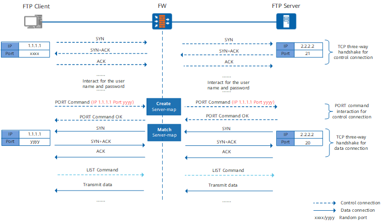
The application-layer information of the PORT command carries the IP address and randomly-opened port of the client. By analyzing the application-layer information of the PORT command, the FW can predict the behavior of subsequent packets and create a server map based on the IP address and port in the application-layer information. After the packet for the server to initiate the data connection to the client reaches the FW, the packet matches the server map entry and is no longer controlled by the security policy.
<sysname> display firewall server-map
Type: ASPF, 2.2.2.2 -> 1.1.1.1:yyyy, Zone: ---
   Protocol: tcp(Appro: ftp-data), Left-Time: 00:00:15
   VPN: public -> public
Port yyyy is the data port opened by the client to the server through the control channel. The data packet for the server (2.2.2.2) to proactively access port yyyy of the client (1.1.1.1) matches the server map and is permitted.
<sysname> display firewall session-table
Current Total Sessions : 2
  ftp  VPN:public --> public 1.1.1.1:xxxx+->2.2.2.2:21
  ftp-data  VPN:public --> public 2.2.2.2:20-->1.1.1.1:yyyy
The multi-channel protocol creates multiple sessions. The control connection and data connection are two different connections. The first session indicates the control connection, +-> indicates that the session enters the ASPF/ALG process. The second session indicates the data connection. A data connection session is created after the packet of the data channel matches the server map.
ASPF in FTP passive mode
In FTP passive mode, the client uses the random port (xxxx) to send a connection request to port 21 on the server to set up a control channel. The client then uses the PASV command to negotiate the port number for the data channel. The negotiated port number is yyyy. After that, the client initiates a data channel request to port yyyy of the server. The server sends data to the client after the data channel is established.
During the security policy configuration, if you permit only the traffic from the client to port 21 of the server, the control connection can be set up. However, after the packet destined from the client to port yyyy on the server arrives at the FW, the packet is not the subsequent packet of the previous connection but of a new connection. To enable the packet to arrive at the server, you must configure a security policy on the FW to permit the packet. Otherwise, the packet cannot pass through the FW, and the data channel fails to be established. As a result, the user can access the server but cannot request data.
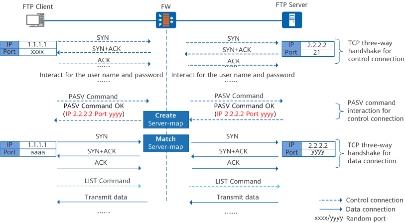
The application-layer information of the PASV Command OK command carries the IP address and randomly-opened port of the server. By analyzing the application-layer information of the PASV Command OK command, the FW can predict the behavior of subsequent packets and create a server map based on the IP address and port in the application-layer information. After the packet for the client to initiate the data connection to the server reaches the FW, the packet matches the server map entry and is no longer controlled by the security policy.
<sysname> display firewall server-map
Type: ASPF, 1.1.1.1 -> 2.2.2.2:yyyy, Zone: ---
   Protocol: tcp(Appro: ftp-data), Left-Time: 00:00:15
   VPN: public -> public
Port yyyy is the data port opened by the server to the client through the control channel. The data packet for the client (1.1.1.1) to proactively access port yyyy of the server (2.2.2.2) matches the server map and is permitted.
<sysname> display firewall session-table
Current Total Sessions : 2
  ftp  VPN:public --> public 1.1.1.1:xxxx+->2.2.2.2:21
  ftp-data  VPN:public --> public 1.1.1.1:aaaa-->2.2.2.2:yyyy
The multi-channel protocol creates multiple sessions. The control connection and data connection are two different connections. The first session indicates the control connection, +-> indicates that the session enters the ASPF/ALG process. The second session indicates the data connection. A data connection session is created after the packet of the data channel matches the server map.
ALG in FTP active mode
- Access from any port of the client to port 21 of the server is allowed for establishing control connections and sending commands.
Access from port 20 of the server to any port of the client is allowed for establishing data connections.
The administrator cannot predict the ports opened on the client, in that they are randomly selected during the negotiation. Therefore, the client needs to have all ports opened, which brings security risks to the client.
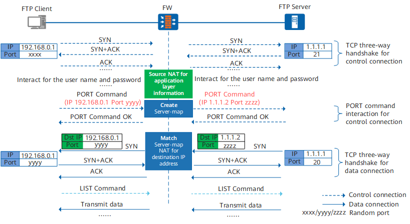
After ALG is configured, the FW analyzes the application-layer information of the PORT command, translates the private address and private network port carried in the command into the public address and public network port, forwards them to the server, and creates a server map. The server initiates a data connection to the translated public address and public network port. After the packet reaches the FW, the packet matches the server map entry, automatically translates the destination address and port into the actual private address, and is no longer controlled by the security policy.

Common NAT translates only transport-layer information of packets, and ALG can also translate application-layer information of packets.
If ALG is configured, you need only to configure the security policy from any port of the client to port 21 of the server on the FW.
<sysname> display firewall server-map
Type: ASPF, 1.1.1.1 -> 1.1.1.2:zzzz[192.168.0.1:yyyy], Zone: ---
   Protocol: tcp(Appro: ftp-data), Left-Time: 00:00:15
   VPN: public -> public
The data packet for the server (1.1.1.1) to proactively access the public address and public port of the client matches the server map and is permitted. In addition, the destination public address and public port are translated into the actual private address (192.168.0.1) and private port (yyyy).
<sysname> display firewall session-table
Current Total Sessions : 2
  ftp  VPN:public --> public 192.168.0.1:xxxx[1.1.1.2:2050]+->1.1.1.1:21
  ftp-data  VPN:public --> public 1.1.1.1:20-->1.1.1.2:zzzz[192.168.0.1:yyyy]
The multi-channel protocol creates multiple sessions. The control connection and data connection are two different connections. The first session indicates the control connection, source NAT is performed on the source address (client address), and +- indicates that the session enters the ASPF/ALG process. The second session indicates the data connection. The data channel packet matches the server map, the destination address is translated into the client's private address, and a data connection session is created.
ALG in FTP passive mode
- Access from any port of the client to port 21 of the server is allowed for establishing control connections and sending commands.
Access from any port of the client to any port of the server is allowed for establishing data connections.
The administrator cannot predict the ports opened on the server, in that they are randomly selected during the negotiation. Therefore, the server needs to have all ports opened, which brings security risks to the server.
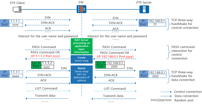
After ALG is configured, the FW analyzes the application-layer information of the PASV Command OK command, translates the private address and private network port carried in the command into the public address and public network port, forwards them to the client, and creates a server map. The client initiates a data connection to the translated public address and public network port. After the packet reaches the FW, the packet matches the server map entry, automatically translates the destination address and port into the actual private address, and is no longer controlled by the security policy.
If ALG is configured, you need only to configure the security policy from any port of the client to port 21 of the server on the FW.
Common NAT translates only transport-layer information of packets, and ALG can also translate application-layer information of packets.
If ALG is configured, you need only to configure the security policy from any port of the client to port 21 of the server on the FW.
<sysname> display firewall server-map
Type: ASPF, 1.1.1.1 -> 1.1.1.2:zzzz[192.168.0.1:yyyy], Zone: ---
   Protocol: tcp(Appro: ftp-data), Left-Time: 00:00:15
   VPN: public -> public
The data packet for the client (1.1.1.1) to proactively access the public address and public port of the server matches the server map and is permitted. In addition, the destination public address and public port are translated into the actual private address (192.168.0.1) and private port (yyyy).
<sysname> display firewall session-table
Current Total Sessions : 2
  ftp  VPN:public --> public 1.1.1.1:xxxx+->1.1.1.2:22[192.168.0.1:21]
  ftp-data  VPN:public --> public 1.1.1.1:aaaa-->1.1.1.2:zzzz[192.168.0.1:yyyy]
The multi-channel protocol creates multiple sessions. The control connection and data connection are two different connections. The first session indicates the control connection, NAT Server is performed on the destination address (server address), and +- indicates that the session enters the ASPF/ALG process. The second session indicates the data connection. The data channel packet matches the server map, the destination address is translated into the server's private address, and a data connection session is created.