Configuring NAT64 Using the Web UI
This section describes how to use the web user interface (UI) to configure dynamic NAT64.
Context
An IPv6 host sends a domain name to a DNS64 server. The DNS64 server resolves the domain name into a destination IPv6 address with a NAT64 prefix and sends the resolution result to the host. The host then sends a request carrying the destination address to a NAT64-enabled FW. Upon receipt of the request, the FW translates the source IPv6 address into an IPv4 address. The IPv6 host can then use the IPv4 address to access the IPv4 network. Figure 1 shows the dynamic NAT64 networking.
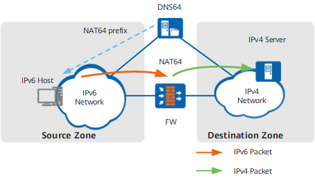

The FW does not support static NAT64 settings on the web UI.
Procedure
- Choose .
- Click Configure in the line of IPv6.
- Select Enable of the IPv6 and NAT64, enable the IPv6 and NAT64 function
- Configure the NAT64 prefix.
Parameter
Description
NAT64 Prefix
The FW checks each received IPv6 packet. If an IPv6 packet contains a NAT64 prefix, the FW performs NAT64 translation on the IPv6 packet. NAT64 prefixes are classified into the following two types:
- Well-known prefix: 64:FF9B::/96.
- Pre-defined prefixes: The prefix length can be 32, 40, 48, 56, 64, or 96 bits.
- Click Apply.
- Choose .
- Click the Source Translation Address Pool tab.
- Click Add and set the following parameters.
Table 1 NAT parameters Parameter
Description
Name
Name of a NAT address pool.
IP Address Range
Start and end public IP addresses that define an IP address range.
The end IP address must be greater than or equal to the start IP address.
You can configure only one public IP address in a NAT address pool so that intranet hosts share a fixed public IP address.
Health Check
You can select a health check template from the drop-down list or create one.
Health check is used to check the validity of a NAT address pool. In a health check, all addresses in the IP Address Range are used as the source addresses.
After the NAT address pool is configured, you can view the Current Health Status of the address pool in Source Translation Address Pool List. If Current Health Status is Partially available, you can click Details to view information about exclusive IP addresses.
Configure Black-Hole Route
If this option is selected, a black-hole route to the NAT address pool is automatically delivered to prevent routing loops. The black-hole route can also be imported to a dynamic routing protocol, such as OSPF, for advertising.
PAT
In addition to source IP addresses, source port numbers can also be translated. Using both source IP address and port number translation can enable intranet hosts to share the same public IP address to access the Internet.
If port translation is disabled, each private address is mapped to a single public address. When all IP addresses in the NAT address pool have been allocated, the FW waits for an available IP address that is released by another host before forwarding the packet.
Advanced
NAT Type
Select a NAT type. The following types are available:- 5-Tuple NAT
- 3-Tuple NAT
This parameter is available only when you set firewall hash-mode to source-only. For configurations on the HASH-based CPU selection mode, see Hash-based CPU Selection.
Translate based on destination zones
Select 3-tuple NAT. If you select this item, local 3-tuple NAT is used; if you do not select this item, global 3-tuple NAT is used.
This parameter is available when you set NAT Type to 3-Tuple NAT.
Allow externally initiated access
If you select this item, a reverse server-map is generated to allow the external access to intranet resources.
This parameter is available when you set NAT Type to 3-Tuple NAT.
Port Pre-allocation
Specify a port range for port pre-allocation.
Port Block Size
Select the size of the allocated port block.
The value is an integer ranging from 8 to 16384.
Incremental Allocations
Select the number of incremental allocations.
The value is an integer ranging from 1 to 3.
Port Range
Select the start port and end port. The values of start port and end port are integers ranging from 256 to 65535.
The scope specified by the start and end ports cannot be smaller than the port block.
If no port range is specified, the default port range (2048 to 65535) is used.
Limit the Number of Source Addresses
If you select this item, set the maximum number of private addresses corresponding to a public address.
If there are too many private addresses, port conflicts may occur when the private addresses are translated into public addresses for Internet access. To reduce the possibility of port conflicts, you must set the maximum number of private addresses corresponding to a public address.
Maximum Number of Source Addresses
Set the maximum number of private addresses corresponding to a public address.
Disable Source Port Translation
If you select this item, port numbers probably remain unchanged during NAT. When packets go through source address translation, the system preferentially keeps the source ports unchanged. If a post-NAT port number has been used, the system randomly allocates a port number to the packet.
This item is displayed if you set NAT Type to 3-Tuple NAT.
Reserved IP Address
Excludes IP addresses from the NAT address pool.
Each address pool has addresses in a maximum of 100 address segments excluded, and each address segment has a maximum of 4096 addresses excluded.
- Click OK.
- Click the NAT Policy tab.
- Click Add and set the following parameters.
Table 2 NAT parameters Parameter
Description
Name
Name of a source NAT policy.
Description
Description of the source NAT policy.
Tag
The tag identifies and categorizes the policy. You can query policies based on tags and delete, move, enable, or disable policies in batches based on the query results. For the tag description and configuration, see Tag.
NAT Type
NAT type:
- NAT
- NAT64
NAT Mode
NAT mode:
- Source address translation.
- Destination address translation.
- Source and destination address translation.
- No translation.
Destination Address Translation Mode
You need to configure this item only when the NAT mode is Destination address translation or Source and destination address translation.
- One-to-one mapping between the public and private addresses in translation: applies to a scenario where a public address is used to access a private address or multiple public addresses are used to access multiple private addresses.
- One-to-one mapping between the public port and private address in translation: applies to a scenario where multiple ports of a public address are used to access multiple private addresses
- One-to-one mapping between the public and private ports in translation: applies to a scenario where multiple ports of a public address are used to access multiple ports of a private address
- One-to-one mapping between the public address and private port in translation: applies to a scenario where multiple public addresses are used to access multiple ports of a private address.
- Randomly translated to an address in the destination translation address pool: applies to a scenario where the destination address is not fixed after NAT. That is, the destination address is randomly translated to an address in the destination translation address pool.
Schedule
Select the period for the security policy to take effect.
- Add New Schedule:
Click Add New Schedule. On the Add New Schedule page, set the period for the security policy to take effect.
- Name: indicates the time range name.
- Type: The value can be Periodic or One Time. Periodic indicates that the policy takes effect during a fixed time range every week. One Time indicates that the policy takes effect only within the specific time range.
- Start Time: indicates the start time of the time range.
- End Time: indicates the end time of the time range.
- Weekly Validity Time: indicates the time range during which the policy takes effect every week. This item is required if Type is set to Periodic.
- any: indicates that the policy takes effect in any time range.
- worktime: indicates that the policy takes effect only within the worktime. You can modify the worktime in or by clicking worktime in Source NAT Policy List.
If a session is created for a service when a policy is valid, the device forwards subsequent packets of the service based on the session even if the policy expires. If the time range is also referenced by another policy, the FW will age the existing session, and therefore the service is interrupted.
Original Data Packet
Source Zone
Name of a security zone to which intranet hosts belong.NOTE:If the matching conditions of the original data packet, including the source security zone, destination security zone/outbound interface, source address, and destination address, are all any, all traffic matches the policy, and NAT is implemented for all traffic. You are advised to configure a more accurate NAT policy.
Destination Type
Destination for traffic that is processed by NAT:
- Destination Zone: performs NAT on traffic that travels from a source security zone to a destination security zone. If Destination Zone is used, select a security zone from the drop-down list.
- Outbound Interface: performs NAT for traffic that travels from a source security zone to a WAN interface. If Outbound Interface is used, select an interface from the drop-down list.
NOTE:Both parameters Destination Zone and Outbound Interface are used to specify the scope of the traffic that requires NAT. You can select either of them to specify the scope of the traffic that requires NAT based on the actual condition.
Source Address
Private IP addresses of intranet hosts. You can select or enter private IP addresses.
If this parameter is specified, the FW only translates IP addresses for traffic with the specified source address.
NOTE:To exclude an address or address group (source address or source addresses of traffic) from policy matching, select the address or address group from the available address area, select it in the selected address area and click Invert, and then click OK.
Destination Address
Address, address group, or domain group.
Enter or select the public IP address to be accessed by intranet hosts. After the configuration, the system performs NAT only on the traffic destined for this address.
Create or select the domain group to be accessed by intranet hosts. After the configuration, the system performs NAT only on the traffic accessing this domain group.
NOTE:To exclude an address or address group (destination address or destination addresses) from policy matching, select the address or address group from the available address area, select it in the selected address area and click Invert, and then click OK.
Service
Name of a service or service group. The service or service group indicates the protocol type of the traffic. After you specify the service or service group, the FW translates the addresses only for traffic of the specified service or service group.
NOTE:To exclude a service or service group (service or service group of traffic) from policy matching, select the service or service group from the available service area, select it in the selected service area and click Invert, and then click OK.
Translated Data Packet
Source Address Translated To
You need to configure this item only when the NAT mode is Source address translation or Source and destination address translation.
Address translation mode:
IP addresses in the NAT address pool: NAT translates private IP addresses into specified addresses in a NAT address pool.
Outbound interface IP address: NAT translates private IP addresses into a specified WAN interface address.
The FW searches for a matching route to locate the WAN interface.
NOTE:Only address pool-based source NAT can be configured on a FW in switched mode (also called transparent mode).
Source Translation Address Pool
You need to configure this item only when the NAT mode is Source address translation or Source and destination address translation.
Source NAT address pool name. You can perform either of the following operations:- Select a specified address pool.
- Click Add Address Pool to configure an address pool.
Destination Address Translation To
You need to configure this item only when the NAT mode is Destination address translation or Source and destination address translation.
Destination NAT address or address pool name. You can perform either of the following operations:
- Select a specified address pool.
- Click Add Address Pool to configure an address pool.
Destination Port Translation Mode
You need to configure this item only when the NAT mode is Destination address translation or Source and destination address translation.
There are two translation modes:
- No translation
- Translation
Destination Port Translated To
You need to configure this item only when the NAT mode is Destination address translation or Source and destination address translation.
Translated port number.
Add Security Policy
The link to [Add Security Policy] is provided on the web UI. You can click the link to access the Add Security Policy page and rapidly create a security policy based on the configured data flows to permit the traffic. In addition, the Add Security Policy page support Switch Source and Destination and OK and Copy for configuring security policies for forward and return traffic. For details, see Configuring a Security Policy Using the Web UI.
- Click OK.