Fault-triggered Switchover and Traffic Diversion
This section describes the fault-triggered switchover and traffic diversion processes in different networking conditions.
If a fault occurs, the new business master device takes over traffic. The original upstream and downstream traffic also needs to be switched to the new master device.

In IPSec scenarios, both the upstream and downstream networks use routes for traffic diversion. In other scenarios, a Layer 3 network uses route-based traffic diversion or service traffic diversion, and a Layer 2 network uses VRRP-based traffic diversion.
Service Traffic Diversion (Connecting to Layer-3 Devices)
Figure 1 shows a typical scenario. FWs perform NAT. A routing protocol, such as OSPF, runs between FWs and routers.

Currently, OSPF, IS-IS, and BGP support route-based traffic diversion. The following services require UNRs: NAT address pools and source addresses of outer IPSec tunnels (the addresses are used to divert packets to devices for IPSec).
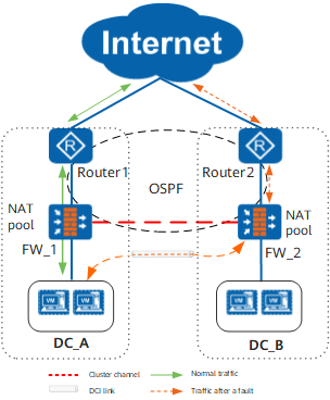
In normal situations, NAT addresses are planned for each DC. Each DC mainly uses certain planned addresses, and address mapping is within the DC. When external hosts access corresponding public addresses, packets arrive at corresponding FWs according to route priorities as expected. If the uplink of FW_1 fails, data of DC_A is forwarded through the backup DC (DC_B). In this case, the route advertised by FW_1 must be synchronized to FW_2 for advertising.
The route-based traffic diversion mechanism is as follows:
- After the cluster function is enabled, the system automatically
generates a routing policy named cluster_rt. The routing policy
configuration is as follows:
#
route-policy cluster_rt permit node 0
 if-match preference 57
 apply cost + 1
#
route-policy cluster_rt permit node 1
 if-match preference 58
 apply cost + 5
#
route-policy cluster_rt permit node 2
 if-match preference 59
 apply cost + 10
#
In the routing policy, associate the UNR priorities with costs.
UNR Priority
Cost Change
57
+1
58
+5
59
+10
When the cluster function is disabled, the system deletes routing policy cluster_rt automatically.
- In a business group, run the ip-section command to specify a UNR advertised by the local DC. Only top three members in a business group advertise UNRs with priorities being 57, 58, and 59 separately.
- In the routing policy, run the import-route unr route-policy cluster_rt command to import UNRs. Use the routing policy to adjust the costs of imported routes, so that the route with the highest priority has the lowest cost.
Route-based Traffic Diversion (Connecting to Layer-3 Devices)
- If the device is in master state, the route cost is not adjusted.
- If the device is the preferential standby device, its route cost increases by one step. The default step is 1000. You can run the cluster adjust add command to change the value.
- If the device is neither the master device nor the preferential standby device in the business group, its route cost increases by two steps.
Currently, business groups can be associated only with OSPF processes. Therefore, route-based traffic diversion applies only to OSPF networks.
The business group adjusts the cost of only a locally advertised route but not a learned route. For OSPF, the cost refers to the Cost value of the route. For BGP, the cost is the MED value of the route.
Figure 2 shows a typical scenario where BGP runs on the upstream network and OSPF runs on the downstream network. Business group 1 is associated with OSPF process 1, and business group 2 is associated with OSPF process 2. OSPF processes 1 and 2 are imported to OSPF on the upstream network.
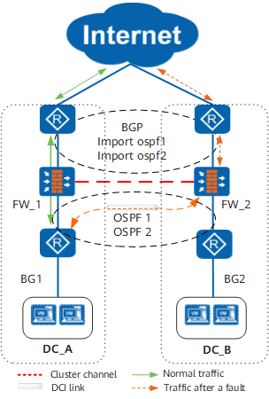
The following table lists the routes advertised by the FW in this example:
Item |
FW_1 | FW_2 |
|---|---|---|
Route to DC_A |
Normally advertised, with an assumed cost of 100 |
1100 (with a default step added) |
Route to DC_B |
1100 (with a default step added) |
Normally advertised, with an assumed cost of 100 |
Take downstream traffic diversion as an example. In normal cases, the host of DC_A accesses the Internet through FW_1. When the downstream link of FW_1 fails, the data of DC_A is forwarded through FW_2.
If the upstream network is OSPF 10, you must specify parameter type 1 and configure default cost inherit-metric when importing OSPF processes 1 and 2 of the downstream network.
<sysname> system-view
[sysname] ospf 10
[sysname-ospf-10] default cost inherit-metric
[sysname-ospf-10] import-route ospf 1 type 1
[sysname-ospf-10] import-route ospf 2 type 1
In BGP, the MED value is not advertised with the route. To adjust the MED value of a business group, run the apply cost command in the routing policy. Adjust the MED value after the apply cost command is executed.
VRRP-based Traffic Diversion (Connecting to Layer-2 Devices)
As shown in Figure 3, each FW serves as an egress gateway for the corresponding DC. The two DCs form a Layer-2 network.
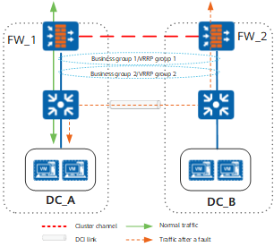
A business group is bound to a VRRP group. If the business group is in the Master state, the VRRP state is Master. In normal situations, traffic is forwarded through the FW in the local DC. If the FW's interface fails, the business group status changes. Then, the VRRP status changes accordingly, and traffic is diverted to the other FW.
Item |
DC_A |
DC_B |
||
|---|---|---|---|---|
Normal Status |
Fault |
Normal Status |
Fault |
|
Business groups |
Business group 1 (bound to VRRP group 1):
Business group 2 (bound to VRRP group 2):
|
Business group 1 (bound to VRRP group 1):
Business group 2 (bound to VRRP group 2):
|
Business group 1 (bound to VRRP group 1):
Business group 2 (bound to VRRP group 2):
|
Business group 1 (bound to VRRP group 1):
Business group 2 (bound to VRRP group 2):
|
VRRP groups |
VRRP group 1:
VRRP group 2:
|
VRRP group 1:
VRRP group 2:
|
VRRP group 1:
VRRP group 2:
|
VRRP group 1:
VRRP group 2:
|
The VRRP-based traffic diversion mechanism is as follows:
- If FW_1's uplink interface fails, the status of business group 1 changes, and FW_2 becomes the business master device.
- The status of business group 1 changes, and the status of VRRP group 1 changes accordingly. FW_2 becomes the master device in VRRP group 1.
- FW_2 sends a gratuitous ARP packet (including the virtual IP address and virtual MAC address of VRRP group 1) to instruct the switch to update the MAC address table.
- The switch receives the ARP packet and updates its MAC address table. Traffic for DC_A is then switched to FW_2.