Understanding GRE
This section describes the GRE encapsulation concepts, GRE packet forwarding process, security policies, and GRE security options.
GRE Encapsulation
All VPN encapsulation technologies, including GRE require a passenger protocol, encapsulation protocol, and transport protocol.
- Passenger protocol:
is the original network protocol used for data transmission.
- Encapsulation protocol:
encapsulates packets of the passenger protocol so that the original packets can be transmitted over the new network.
- Transport protocol:
is the network protocol used to transmit encapsulated packets over the new network.
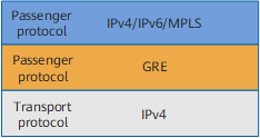
Figure 1 shows the protocol stack of GRE used on the FW. The passenger protocol can be IPv4, IPv6, and MPLS, and the transport protocol is IPv4.
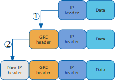
GRE encapsulates packets layer by layer according to the protocols stack, as shown in Figure 2. The encapsulation process contains two steps. The first step adds a GRE header to the original packet, and the second step adds a new IP header in the front of the GRE header. After the second step is complete, the original packet can be transmitted over the new network. GRE encapsulation is completed by a tunnel interface. The tunnel interface is a common logical interface. The encapsulation protocol needs to be set to GRE for the tunnel interface.
GRE Packet Forwarding Process
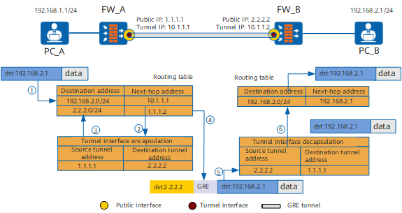
- After receiving the original packet sent by PC_A to PC_B, FW_A searches its routing table for a matching route.
- According to the search result, FW_A sends the packet to the tunnel interface for GRE encapsulation. The tunnel interface adds a GRE header and then a new IP header before the GRE header.
- FW_A searches its routing table again for a matching route based on the destination address (2.2.2.2) in the new IP header of the GRE packet.
- FW_A forwards the GRE packet based on the matching route to FW_B. In the above figure it is assumed that the next-hop address found by FW_A for FW_B is 1.1.1.2.
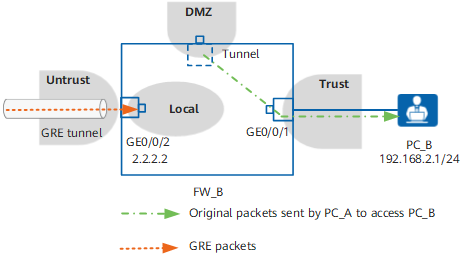
- After receiving the packet, FW_B determines whether the packet is a GRE packet.
As shown in Figure 1, the new IP header in the GRE packet has the Protocol field. If the Protocol field value is 47, the packet is a GRE packet. If the packet is a GRE packet, FW_B forwards the packet to the tunnel interface for decapsulation. The tunnel interface removes the IP header and GRE header in sequence to restore the original packet. If the packet is not a GRE packet, FW_B forwards the packet as a common packet.
- FW_B searches its routing table from a matching route based on the destination address of the original packet and then forwards the packet based on the matching route to PC_B.
Security Policy
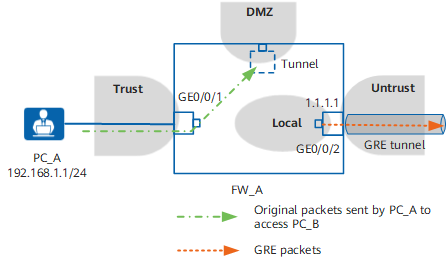
Service Direction |
Device |
Source Zone |
Destination Zone |
Source Address |
Destination Address |
Application |
|---|---|---|---|---|---|---|
From PC_A to PC_B |
FW_A |
Trust |
DMZ |
192.168.1.0/24 |
192.168.2.0/24 |
* |
Local |
Untrust |
1.1.1.1/32 |
2.2.2.2/32 |
GRE |
||
FW_B |
Untrust |
Local |
1.1.1.1/32 |
2.2.2.2/32 |
GRE |
|
DMZ |
Trust |
192.168.1.0/24 |
192.168.2.0/24 |
* |
GRE Security Options
To enhance GRE security, the devices at both ends of a GRE tunnel authenticate each other's identity. The devices negotiate a key in advanced. During GRE packet transmission, the key is encapsulated in the GRE header. After receiving GRE packets from each other, the devices compare the key in the GRE packets with their own one. If the keys are the same, the authentication succeeds. If the keys are different, the authentication fails, and the packet is discarded. In the GRE header, key flag 1 indicates that identity authentication is enabled, and key flag 0 indicates that identity authentication is disabled. Identify authentication is disabled by default on the FW.
Automatic TCP-MSS Adjustment
The device supports dynamic adjustment in the maximum segment size (MSS) of SYN or SYN-ACK packets during TCP connection setup.
Background
During TCP connection setup, the Option of SYN or SYN-ACK packets may carry the MSS field to inform the peer device of the maximum segment size that the local device can receive. After the MSS values are exchanged and compared, the smaller MSS value is selected for forwarding packets to ensure that the network involves no packet fragmentation. If fragmentation does not exist, the larger the MSS value, the greater the amount of data sent per segment, and the higher the network usage. Proper MSS value adjustment can minimize the possibility of fragmentation and promote the transmission of large data packets to improve end-to-end TCP transmission efficiency.
Implementation Mechanism
If a SYN or SYN-ACK packet does not have an MSS field, the device automatically inserts an appropriate MSS value:
MSS=MTU-40–APPENDLEN
MSS indicates the MSS value that is automatically inserted. MTU indicates the maximum transmission unit of the interface. APPENDLEN indicates the packet length added during VPN encryption and encapsulation.
- If a SYN or SYN-ACK packet has an MSS field, the device compares MSS-APPENDLEN with MTU-40-APPENDLEN and changes the overly large MSS value to a smaller value.
- If MTU-40-APPENDLEN is larger than MSS-APPENDLEN, the original MSS value is reserved and used.
- If MTU-40-APPENDLEN is smaller than MSS-APPENDLEN, MTU-40-APPENDLEN is used as the new MSS value.
Restrictions
- MTU values of interfaces through which the VPN passes must be the same.
- Automatic TCP-MSS adjustment is performed only when the MTU value of the interface ranges from 256 to 9600.
- This function is supported by the IPSec, GRE, and L2TP services but not the L2TP over IPSec or GRE over IPSec service.