Interface Name
|
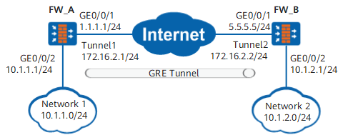
Name of the GRE interface. The value must be unique on a device. In Figure 1, Tunnel1 is a GRE interface.
|
Virtual System
|
Displays the virtual system to which the tunnel interface belongs. When you create a tunnel interface, the interface belongs to root system public.
To configure GRE multi-instances, choose to create a virtual system and allocate interfaces. For details, see Creating a Virtual System and Allocating Resources.
|
Zone
|
Security zone to which the GRE interface is to be assigned. You are advised to assign the GRE interface and tunnel source interface (WAN interface) to the same security zone. If you assign them to different security zones, you must configure a security policy to allow hosts in the security zones to communicate.
|
IP Address/Mask
|
IP address and mask of the GRE interface. You are advised to set the IP addresses of the GRE interfaces at both ends to be on the same subnet. In Figure 1, the address of the GRE interface on FW_A is 172.16.2.1.
NOTE: The link to [Add Security Policy] is provided on the web UI. You can click the link to access the Add Security Policy page and rapidly create a security policy based on the configured data flows to permit the traffic. In addition, the Add Security Policy page support Switch Source and Destination and OK and Copy for configuring security policies for forward and return traffic. For details, see Switching the Source and Destination.
|
Source Address Configuration
|
Method of setting the source address of the GRE interface.
- IP Address: Enters an IP address as the source address of the GRE interface.
- Interface: Uses the IP address of a physical interface or local loopback interface as the source address of the GRE interface.
|
Source IP Address
|
IP address of the tunnel source interface (WAN interface) or local loopback interface, for example, 1.1.1.1 in Figure 1.
Source IP Address on the local end must be the same as Destination IP Address on the peer end.
When Source Address Configuration is set to IP Address, the Source IP Address parameter is displayed.
|
Interface
|
Tunnel source interface (WAN interface) or local loopback interface, for example, GE0/0/1 in Figure 1.
When Source Address Configuration is set to Interface, the Interface parameter is displayed.
|
Destination Address Configuration
|
Method of setting the destination address of the GRE interface.
- IP Address: Enters an IP address as the destination address of the GRE interface.
- Domain: When the peer IP address is unfixed, bind it to the domain name on the network, and specify the domain name bound with the peer IP address at the local end.
|
Destination IP Address
|
IP address of the tunnel destination interface (WAN interface) or peer loopback interface, for example, 5.5.5.5 in Figure 1.
The Destination IP Address on the local end must be the same as the Source IP Address on the peer end.
When Destination Address Configuration is set to IP Address, the Destination IP Address parameter is displayed.
NOTE: The link to [Add Security Policy] is provided on the web UI. You can click the link to access the Add Security Policy page and rapidly create a security policy based on the configured data flows to be encrypted to permit encrypted traffic. In addition, the Add Security Policy page support Switch Source and Destination and OK and Copy for configuring security policies for forward and return traffic. For details, see Switching the Source and Destination.
|
Domain
|
Destination domain name of the GRE interface. The domain name must be bound with the IP address of the tunnel destination interface (WAN interface).
|
Multi-egress options
|
After you select Multi-egress options, the interface will function as an intelligent uplink selection member interface.
For details on intelligent uplink selection, see Intelligent Uplink Selection.
|
Carrier
|
Select the name of the ISP directly connected to the interface.
Selecting the ISP of the interface equals to binding an interface to an ISP interface group.
|
Carrier Route
|
After you enable the ISP route function, the FW will generate static routes in a batch to the ISP network. In the generated static routes, the destination is an IP address in the ISP address file, and the next hop is the gateway address specified on the outbound interface. These static routes are called ISP routes. They have the same priority as common static routes, and the default priority is 60.
Choose . You can view the generated ISP route entries.
|
Sticky load balancing
|
In the multi-ISP load balancing NAT server scenario, the FW looks up the routing table for an outgoing interface to send the return traffic from a server. As a result, the return traffic from the server may take a path on ISP2, although the request to the server takes a link on ISP1. The inconsistent forward and return paths may slow down or even interrupt services. To resolve this issue, configure the sticky load balancing function on the incoming interface of ISP1.
The FW uses the incoming interface of the forward packets as the outgoing interface of return packets instead of looking up the routing table.
NOTE: If equal-cost multipath (ECMP) routes are configured, the sticky load balancing function is enabled by default. Otherwise, configure the sticky load balancing function.
|
Health Check
|
Apply the health check to the interface.
|
Source IP Address for Link Check
|
Source IP address of the quality detection packet.
NOTE: The quality detection source IP address and Tunnel interface IP address must reside on the same subnet and must be available and routable IP addresses. The quality detection source IP address must be permitted by the IPSec ACL rules to enter the tunnels. Otherwise, the quality detection result does not indicate the transmission quality of the IPSec tunnels.
|
Advanced
|
GRE Checksum
|
GRE tunnel checksum function. If this function is configured on the local end but not the peer end, the local end calculates the checksum of packets it sends, but does not check the checksum of received packets. If this function is configured on the peer end but not the local end, the local end checks the checksum of packets sent by the peer end, but does not calculate the checksum of packets it sends.
|
GRE Key
|
Tunnel authentication keyword function. The authentication keywords at both ends must be the same. Otherwise, packets cannot be authenticated and are discarded.
|
Keep-alive Function
|
If the keepalive function is enabled but the remote device is unreachable, the local VPN will not select the GRE tunnel to avoid data loss. If Destination Address Configuration is set to Domain, you must enable the keeplive function.
|
Period
|
Interval for sending keepalive packets.
|
Retry Times
|
If the number of keepalive packets that the device sends exceeds the specified value but the device does not receive any reply from the peer device, it determines that the peer device is unreachable.
|
MTU
|
Maximum transmission unit of the interface. After the MTU of an interface is modified, you need to restart the interface to validate the MTU.
This parameter can only be set when Mode is set to Route.
|