This section describes how to configure GRE on the CLI.
Prerequisites
Before configuring GRE, complete the following tasks:
- Set interface IP addresses and assign the interfaces to security zones.
- Configure routes to ensure IP connectivity.
- Configure security policies to ensure the communication between networks.
Context
Figure 1 GRE networking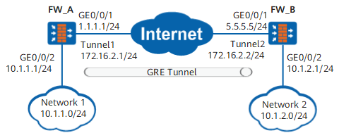
By referencing Figure 1, the administrator can complete the following operations on the two ends of the GRE tunnel.
Procedure
- Configure the tunnel interface.
- Access the system view.
system-view
- Create a tunnel interface and access the tunnel interface view.
interface tunnel interface-number
- Set the IP address of the tunnel interface.
ip address ip-address { mask | mask-length }
You are advised to set the IP address of the local tunnel interface to be on the same subnet as that of the peer tunnel interface.
You can run the ip address unnumbered interface interface-type interface-number command to set the IP address of the tunnel interface using IP address unnumbered. Usually, the tunnel interface uses the IP address of the local WAN interface or loopback interface.
- Set the tunnel mode of the tunnel interface to GRE.
tunnel-protocol gre
You must run the tunnel-protocol gre command before running any GRE tunnel command.
The default tunnel mode of the tunnel interface is none.
- Set the source address or source interface of the tunnel interface.
source { source-ip-address | interface-type interface-number }
- source-ip-address specifies the IP address of the tunnel source interface (WAN interface, for example, GE0/0/1 of FW_A in Figure 1) or local loopback interface.
- source-ip-address on the local end must be the same as dest-ip-address on the peer end.
- interface-number is usually the tunnel source interface (WAN) or local loopback interface.
- Set the destination address or domain name of the tunnel interface.
destination { [ vpn-instance vpn-instance-name ] dest-ip-address | domain domain-name }
- dest-ip-address specifies the IP address of the tunnel destination interface (WAN interface, for example, GE0/0/1 of FW_B in Figure 1) or peer loopback interface.
- dest-ip-address on the local end must be the same as the source-ip-address on the peer end.
- If domain domain-name is selected, run the keepalive command in the tunnel interface view. This ensures that the change of the peer DNS domain name or IP address is synchronized to the local end in real time.
- If domain domain-name is specified, the destination IP address of the GRE tunnel is still the IP address saved in the cache within the TTL of the DNS application cache (1 hour by default). To adjust the TTL of the DNS application cache, run the dns application cache ttl command to configure the maximum and minimum TTL values of the DNS application cache.
- Optional: Set the interface MTU.
mtu mtu-value
To change the MTU of the tunnel interface, run the mtu mtu-value command first.
You are advised to set the MTU of the tunnel interface to be smaller than that of the MTU of the tunnel source interface (WAN interface) minus the length of the encapsulated packet header (GRE header+new IP header).
- Optional: Enable the GRE keepalive function.
keepalive [ period period ] [ retry-times retry-times ]
- By default, the GRE keepalive function is disabled.
After the GRE keepalive function is enabled, the local end periodically sends keepalive packets to the peer end to detect the status of the GRE tunnel. If the peer end is not routable, the local tunnel interface is brought down. This avoids the data blackhole resulted from an unreachable peer end.
- period specifies the interval at which the local end sends keepalive packets. If the local end does not receive any reply from the peer end within the specified local retry-times, it considers the peer end as unreachable.
The GRE keepalive function is unidirectional. The local keepalive function takes effect even if the peer end does not support or enable the keepalive function. You are advised to enable the keepalive function on both ends of the GRE tunnel.
- Return to the system view.
quit
- Optional: Enable the GRE packet pre-fragmentation function.
tunnel gre smart-fragment enable
By default, the GRE packet pre-fragmentation function is disabled.
To ensure that the physical interface of the tunnel interface does not fragment packets after GRE encapsulation, the MTU of the tunnel interface must use the smaller value of the following: 1. the configured tunnel interface MTU, 2. the value obtained by deducting the GRE header length from the physical interface MTU. Therefore, the actual tunnel interface MTU is always smaller than or equal to the second value. Even though the GRE packet is larger than the physical interface MTU after GRE encapsulation, the device will fragment the GRE packet on the tunnel interface in advance. This is the GRE packet pre-fragmentation function. Therefore, when the GRE packet pre-fragmentation function is enabled, the tunnel interface MTU may not be the same as the configured MTU. If you need to keep the tunnel interface MTU the same as the configured MTU, run the undo tunnel gre smart-fragment enable command to disable the GRE packet pre-fragmentation function.
- Access a security zone view.
firewall zone [ name ] zone-name
- Assign the tunnel interface to the security zone.
add interface tunnel tunnel-number
You are advised to assign the tunnel interface and tunnel source interface (WAN interface) to the same security zone. If you assign them to different security zones, you must configure a security policy to allow hosts in the security zones to communicate.
- Return to the system view.
quit
- Optional: Configure the GRE security options.
- Access the tunnel interface view.
interface tunnel interface-number
- Configure the GRE packet checksum function.
gre checksum
By default, the GRE checksum function is disabled.
- Configure the authentication key function of the tunnel interface.
gre key key-number or gre key { cipher key-number | plain key-number }
By default, the authentication key function of the tunnel interface is disabled.
If you set key-number for both ends of the tunnel, specify the same value. You can also leave this parameter unspecified on both ends.
- Configure a route on the tunnel interface using either a static route or dynamic route as follows:
Static Route
Configure static routes.
ip route-static dest-ip-address { mask | mask-length } tunnel interface-number [ nexthop-address ] [ preference preference ] [ track ip-link link-id ] [ description text ]
- The destination address of the static route is the destination address of the packet before GRE encapsulation. This address cannot be on the same subnet as the IP address of the tunnel interface.
- The outgoing interface of the static route is the local tunnel interface.
As shown in Figure 1, the destination address of the static route on the FW is the address of Network 2, and the outgoing interface is Tunnel 1.
[FW_A] ip route-static 10.1.2.0 255.255.255.0 tunnel 1
Dynamic Route
Enable the dynamic routing protocol on the tunnel interface and LAN interface. The dynamic routing protocol sets up the route entries for packets whose outgoing interface is the tunnel interface.
As shown in Figure 1, interfaces Tunnel 1 and GE0/0/1 use OSPF process 1.
[FW_A] ospf 1
[FW_A-ospf-1] area 0
[FW_A-ospf-1-area-0.0.0.0] network 172.16.2.0 0.0.0.255
[FW_A-ospf-1-area-0.0.0.0] network 10.1.1.0 0.0.0.255
[FW_A-ospf-1-area-0.0.0.0] quit
[FW_A-ospf-1] quit
Follow-up Procedure
Run the display interface tunnel [ interface-number ] command to check the running status of the tunnel interface.