Binding NAT Server to VRRP
In active/standby mode, you do not need to manually bind the NAT Server to the VRRP group. In load balancing hot standby, if the public IP address of NAT Server and the IP address of the VRRP group are not on the same network segment, you do not need to manually bind the NAT address pool to the VRRP group. If the public IP address of NAT Server and the IP address of the VRRP group are on the same network segment, you need to manually bind the NAT Server to the VRRP group.
Prerequisites
Before you bind NAT server to a VRRP group, ensure that:
- Hot standby has been configured on the FWs.
- The NAT policy configured on the active FW has been backed up to the standby FW.
Binding NAT Server to VRRP Groups in Active/Standby Mode
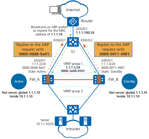
As shown in Figure 1, upon receiving a packet from an Internet user to the intranet, the FW translates the packet destination IP address to an IP address after NAT Server.
If the NAT Server address resides on the same subnet as the IP address of the VRRP group on the upstream interface of the FW, the Router broadcasts an ARP packet to request for the MAC address corresponding to the NAT Server address after receiving the return packet from the intranet.
The two FWs have the same NAT Server configuration. Therefore, both of them reply the MAC addresses of their upstream interfaces to the Router.
As a result, the Router may sometimes encapsulate return packets with the MAC address of the upstream interface on FW_A and send the return packets to FW_A, and sometimes encapsulate return packets with the MAC address of the upstream interface on FW_B and send the return packets to FW_B, which apparently affects normal service processing.
In such scenarios, you need to bind NAT Server to the VRRP groups on the FWs.
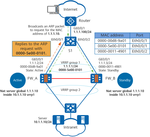
As shown in Figure 2, after the configuration is complete, only the firewall with the active VRRP group (FW_A) can reply to the ARP request from the Router. FW_A replies the virtual MAC address (for example, 0000-5e00-0101) of the VRRP group in the ARP reply packet to the Router. As a result, all packets from Internet users to the intranet are forwarded only to FW_A.
The system can automatically bind NAT Server to the VRRP group with the smallest VRID if the NAT Server and VRRP group reside on the same subnet. Therefore, in active/standby mode, you do not need to manually bind NAT Server to any VRRP groups.
Binding NAT Server to VRRP Groups in Load Balancing Mode
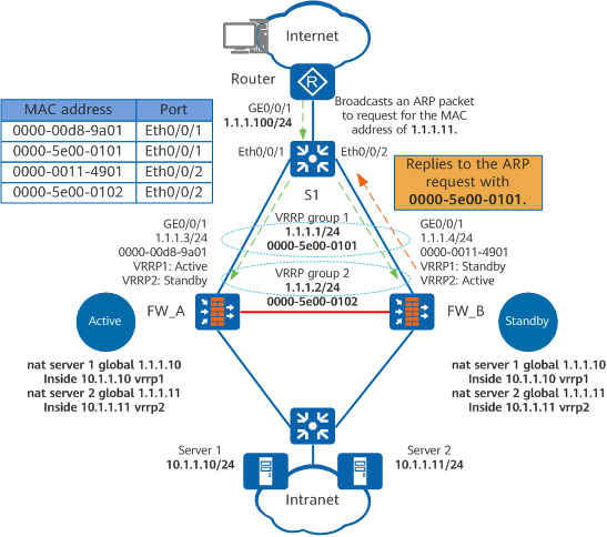
As shown in Figure 3, two firewalls back up each other in load balancing mode. VRRP group 1 on FW_A is in Active state, and VRRP group 2 on FW_B is also in Active state. To enable the FWs to forward traffic concurrently, bind NAT Server1 to VRRP group 1 (command: nat server global 1.1.1.10 inside 10.1.1.10 vrrp 1) and NAT Server2 to VRRP group 2 (command: nat server global 1.1.1.11 inside 10.1.1.11 vrrp 2). Then the packets from Internet users to intranet server 1 will be forwarded to FW_A, and the packets from Internet users to intranet server 2 will be forwarded to FW_B.
Procedure
- Access the system view.
system-view
- Configure NAT Server.
nat server [ name ] [ vpn-instance vpn-instance-name1 ] global { global-address [ global-address-end ] | interface interface-type interface-number } inside host-address [ host-address-end ] [ vrrp virtual-router-id ] [ no-reverse ] [ vpn-instance vpn-instance-name2 ] [ description description ]
For example:
nat server global 1.1.1.10 inside 10.1.1.10 vrrp 1
nat server global 1.1.1.11 inside 10.1.1.11 vrrp 2