Implementing Hot Standby in Active/Standby Mode Using Dynamic Routing
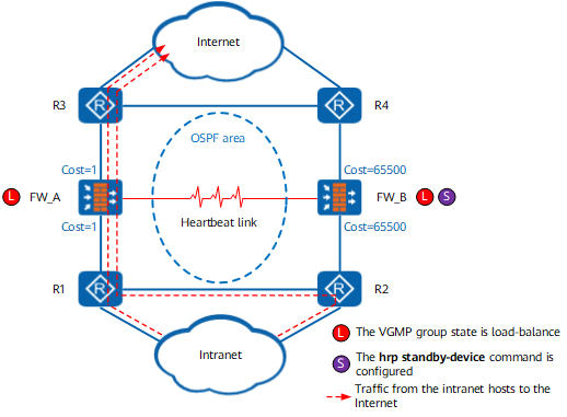
On the network shown in Figure 1, to enable two FWs to work in active/standby mode, run the hrp standby-device command on one FW to specify the FW as the standby FW. For example, run the hrp standby-device command on FW_B in Figure 1. In this way, when the two FWs work normally, FW_A advertises routes according to the OSPF configuration. The cost of the OSPF routes advertised by FW_A is changed to 65500 (the default value, which can be changed to other values). The cost of the link where the FW_A resides is far smaller than the cost of the link where the FW_B resides. When forwarding traffic, a router selects a path with a smaller cost. Therefore, traffic between the intranet and Internet is diverted to FW_A for forwarding.
As shown in Figure 2, the upstream service interface of the FW_A is faulty. The state of the VGMP group changes to standby on FW_A and to active on FW_B. FW_A and FW_B adjust the OSPF costs based on the VGMP group status. The cost of the OSPF routes advertised by FW_A is changed to 65500, and the cost of the OSPF routes advertised by FW_B is changed to 1. After route convergence is complete, traffic between the intranet and Internet is diverted to FW_B for forwarding.
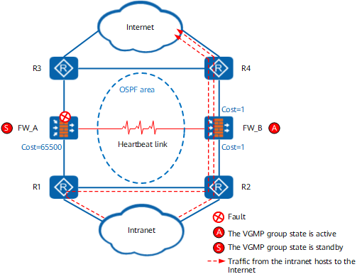
In conclusion, only FW_A processes the traffic between the intranet and Internet in normal conditions. FW_A and FW_B work in active/standby mode. FW_A is the active device and FW_B is the standby device. When FW_A is faulty, FW_B automatically takes over the traffic between the intranet and Internet to ensure service continuity.