Controlling VLAN Status Using VGMP Group
After the hot standby function is enabled, the FWs can enable or disable VLAN based on the VGMP group status. The detailed procedure is as follows:
- By default, the FWs do not adjust the status of any VLAN based on the VGMP group status. After you run the hrp track vlan vlan-id command to configure a VGMP group to monitor the VLAN status, the FWs adjust the VLAN status based on the VGMP group status.
- When the VGMP group is in the active state, the FWs enable the VLAN monitored by the VGMP group so that the VLAN can forward packets.
- When the VGMP group is in the standby state, the FWs disable the VLAN monitored by the VGMP group so that the VLAN cannot forward packets.
- When the state of a VGMP group is load-balance, the FW enables the VLAN monitored by the VGMP group by default. If you run the hrp standby-device command on a FW to specify the FW as the standby device or set the status of all VRRP groups on the FW to standby, the FW disables the VLAN monitored by the VGMP group.
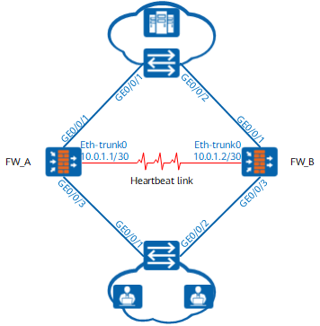
The networking diagram in Figure 1 is an example to describe how the FWs adjust the VLAN status based on the VGMP group status. Table 1 describes the key configurations of FW_A and FW_B in Figure 1.
FW_A |
FW_B |
|---|---|
# hrp enable /*Enable hot standby.*/ hrp interface eth-trunk0 remote 10.0.1.2 /*Configure the heartbeat interface.*/ hrp track vlan 10 /*Configure VGMP to monitor VLAN status.*/ # interface GigabitEthernet 0/0/1 portswitch port link-type trunk port trunk allow-pass vlan 10 /*Configure the interface to permit the VLAN.*/ undo port trunk allow-pass vlan 1 # interface GigabitEthernet 0/0/3 portswitch port link-type trunk port trunk allow-pass vlan 10 /*Configure the interface to permit the VLAN.*/ undo port trunk allow-pass vlan 1 |
# hrp enable /*Enable hot standby.*/ hrp interface eth-trunk0 remote 10.0.1.1 /*Configure the heartbeat interface.*/ hrp track vlan 10 /*Configure VGMP to monitor VLAN status.*/ hrp standby-device /*Configure the device as a standby device.*/ # interface GigabitEthernet 0/0/1 portswitch port link-type trunk port trunk allow-pass vlan 10 /*Configure the interface to permit the VLAN.*/ undo port trunk allow-pass vlan 1 # interface GigabitEthernet 0/0/3 portswitch port link-type trunk port trunk allow-pass vlan 10 /*Configure the interface to permit the VLAN.*/ undo port trunk allow-pass vlan 1 |
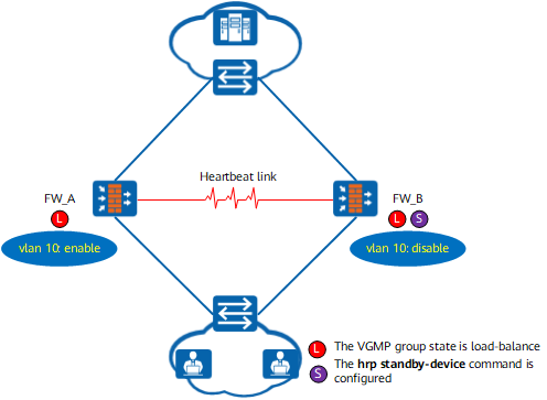
As shown in Figure 2, neither FW_A nor FW_B is faulty, the VGMP groups have the same priority, and the VGMP groups are in the load-balance state. VLAN 10 is enabled on FW_A. VLAN 10 is disabled on FW-B because the hrp standby-device command is configured on the device.
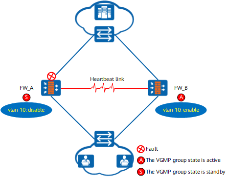
As shown in Figure 3, the upstream service interface of FW_A is faulty, and FW_B is normal. The VGMP group priority of FW_A is lower than that of FW_B. The VGMP group of FW_A becomes standby, and that of FW_B becomes active. VLAN 10 is disabled on FW_A. VLAN 10 is enabled on FW_B.