Hot Standby in Transparent Mode When the FWs Are Connected to Switches in the Upstream and Downstream
As shown in Figure 1, the upstream and downstream interfaces on the FWs work at Layer 2 and are connected to switches. The uplink and downlink service interfaces of the FWs and the switch ports connected to the FWs are added to VLAN 10.
In this networking, it is recommended that the two FWs work in active/standby mode instead of in load balancing mode. A Layer 2 loop is formed between the FWs and the switches. To eliminate the loop, the link where a FW resides needs to be blocked. That is, the traffic between the intranet and Internet can be forwarded only through one of the two FWs at the same time. When the FWs work in load balancing mode, VLANs on the two FWs are enabled and can forward traffic. In this case, a loop prevention protocol needs to be configured on the switches to eliminate Layer 2 loops.
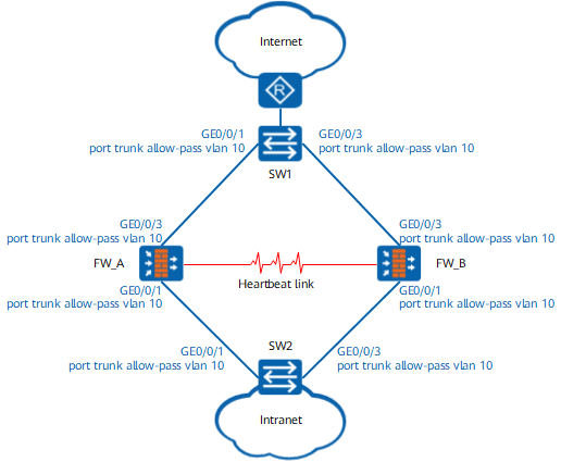
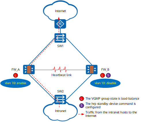
On the network shown in Figure 1, to enable the two FWs to work in active/standby mode, run the hrp standby-device command on one FW to specify the FW as the standby FW. Run the hrp track vlan command on the two FWs to configure the VGMP group to monitor the VLANs to which the interfaces are added. As shown in Figure 2, the hrp standby-device command is configured on FW_B and is specified as the standby device. When both FWs are normal, VLAN 10 is disabled on FW_B because the hrp standby-device command is configured on the device. The hrp standby-device command is not configured on FW_A. Therefore, VLAN 10 is enabled on the device. The upstream and downstream switches can learn MAC addresses only from interfaces connected to FW_A. Therefore, traffic is diverted to FW_A for processing.
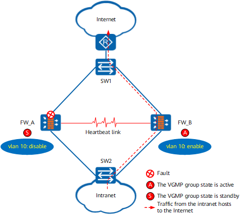
As shown in Figure 3, the upstream service interface of FW_A is faulty. The state of the VGMP group changes to standby on FW_A and to active on FW_B. FW_A and FW_B adjust the VLAN status based on the VGMP group status. VLAN 10 is disabled on FW_A and enabled on FW_B. In addition, all interfaces added to VLAN 10 on FW_A go Down and then Up, triggering the deletion of the MAC address entry on the upstream and downstream switches. When packets reach the switches, the packets are flooded in VLAN 10 because there is no MAC address entry to match. After the packets are flooded once, the upstream and downstream switches learn the MAC address entry from the interface connected to FW_B, and the subsequent traffic is diverted to FW_B for processing.