Hot Standby in Transparent Mode When the FWs Are Connected to Routers in the Upstream and Downstream
As shown in Figure 1, the upstream and downstream service interfaces of the FWs work at Layer 2 and are connected to routers. OSPF runs between routers, and FWs transparently transmit OSPF packets from routers.
To enable the two FWs to work in active/standby mode, configure OSPF route costs on the upstream and downstream routers so that traffic is forwarded through only one FW. As shown in Figure 1, R2 has two paths to reach the Internet: (1) R2->FW_B->R4 (2) R2->R1->FW_A->R3. The cost of path (1) is 200, the cost of path (2) is 110, which is smaller. That is, in the two paths from R2 to the Internet, the path via FW_A is better. Similarly, for the other routers, the path via FW_A is better. In this way, the traffic between the intranet and Internet is diverted to FW_A for forwarding. FW_A and FW_B work in active/standby mode. FW_A is the active device and FW_B is the standby device.
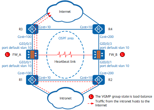
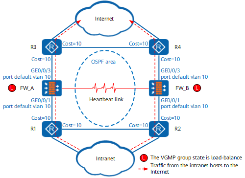
To enable the two FWs to work in load balancing mode, configure OSPF route costs on the FWs and upstream and downstream routers to evenly distribute traffic to the two FWs. As shown in Figure 2, the cost of OSPF routes on the router is set to 10. R2 has two paths to reach the Internet: (1) R2->FW_B->R4 (2) R2->R1->FW_A->R3. The cost of path (1) is 10, the cost of path (2) is 20, which is larger. That is, in the two paths from R2 to the Internet, the path via FW_B is better. In the two paths (R1->FW_A->R3 and R1->R2->FW_B->R4) from R1 to the Internet, the path via FW_A is better. In this way, the traffic from the intranet to the Internet is processed by FW_A and FW_B.
Similarly, the traffic from the Internet to the intranet is also processed by FW_A and FW_B. FW_A and FW_B work in load balancing mode.
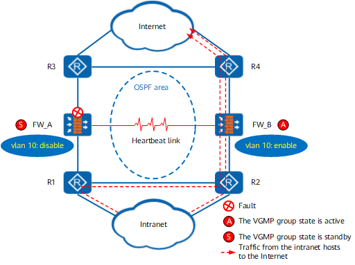
In this networking, you also need to run the hrp track vlan command on the FWs to configure the VGMP group to monitor the VLAN to which the interfaces are added. The reasons are as follows: After you run the hrp track vlan command to configure a VGMP group to monitor the VLAN to which the interfaces are added. When an interface in the VLAN fails, other interfaces in the VLAN go down and then go up. This mechanism speeds up route convergence between the upstream and downstream routers. For example, if the upstream service interface of FW_A in Figure 3 is faulty, the downstream service interface goes down and then up. Router R1 can immediately detect the change of the network topology and start route convergence.