Web: Example for Configuring IDS Interworking with the NIP
This section provides an example for configuring the interworking with IDS.
Networking Requirements
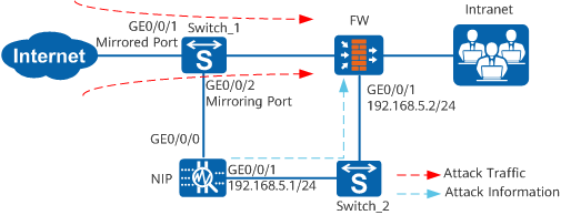
The FW and IDS (NIP in this example) work together to secure the intranet, as shown in Figure 1.
The NIP records network events, including attacks and unusual behavior (such as worms and Trojan horses), unusual network access, and misuse and abuse of network services in real time. When the NIP detects attacks or unusual behavior, the NIP delivers the attack information to the FW, and the FW blocks the attack traffic.
Data Planning
Item |
Data |
|---|---|
FW |
|
NIP |
|
Configuration Roadmap
- Set IP addresses for interfaces and assign the interfaces to security zones.
- Configure security policies.
- Specify the interface IP addresses of the IDS.
- Specify the port for the FW to communicate with the NIP.
- Configure the authentication mode and key for the FW.
- Configure the NIP.
Procedure
- Configure the port mirroring function on Switch_1.
The Huawei Technologies Co., Ltd. S5300 switch is used as an example to illustrate how to configure port mirroring. For configuration of other functions, refer to the product documents of the S5300 switch.
- Configure the FW.
- Complete the basic configurations of the FW.
- Choose .
- Click
 of GE0/0/1,
set required parameters, and click OK.
of GE0/0/1,
set required parameters, and click OK.
IP address
192.168.5.2
Subnet mask
255.255.255.0
Security zone
Trust
- Configure security policies to ensure basic network
communication.
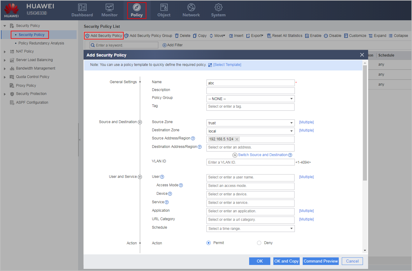
# Configure the Trust-to-Local interzone security policy to allow the IDS to access the local zone and instruct the FW to take actions.
- Choose .
- Click Add.
- Set the parameters for the security policy as listed in the following
table.
Name
abc
Source zone
trust
Destination zone
local
Destination address
192.168.5.1/24
Action
Allow
- Click OK.
- Choose .
- Enable the blacklist function.
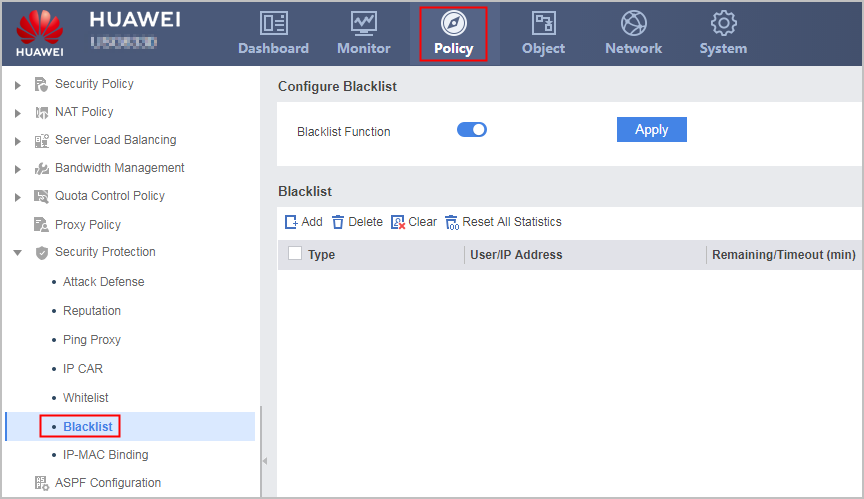
- Choose .
- Enable Blacklist Function and click Apply.
- Complete the interworking configuration.
- Choose .
- Set parameters for the interworking with the IDS and click Apply.
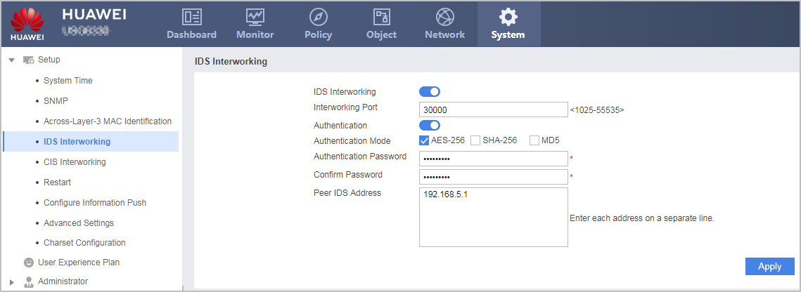

The IDS IP address, port number, and authentication method and key specified on the FW must be the same as those on the IDS.
- Complete the basic configurations of the FW.
- Configure the NIP.
Set the IP address of the FW to 192.168.5.2, port number to 30000, authentication method to AES256, and authentication key to Admin@123.
Configuration Scripts
Configuration script of the FW
#
 firewall ids authentication type aes256 key %$%$!^8fKr$NsR&Vql.7E`mIjJA8%$%$
 firewall ids client 192.168.5.1
 firewall ids port 30000
 firewall ids enable
#
interface GigabitEthernet 0/0/1
ip address 192.168.5.2 255.255.255.0
#
firewall zone trust
 set priority 85
 add interface GigabitEthernet 0/0/1
#
security-policy
  rule name abc
    source-zone trust
    destination-zone local
    source-address 192.168.5.1 24
    destination-address any
    service any
    user any
    application any
    time-range any
    action permit
#
firewall blacklist enable
#
return