CLI: Example for Configuring the Interworking Between IP-Link and Hot Standby
This section describes how to configure the interworking between IP-link and hot standby according to the example for configuring active/standby hot standby.
Network Requirements
The FW is deployed on the service node as a security device. Upstream and downstream devices are routers. FW_A and FW_B work in active/standby mode
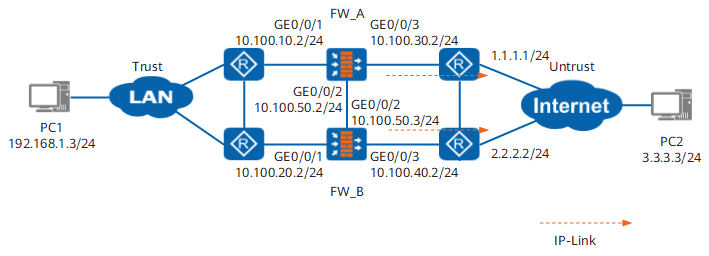
Figure 1 shows the networking diagram. The detailed description is as follows:
- OSPF is applied among the router and two FWs. The router sends service packets to the Active FW according to the route calculation result.
- The upstream and downstream ports of the FW are added to the same link-group. The route convergence rate is accelerated if a link is faulty.
- FW monitor the network egress through the interworking function between IP-link and hot standby. When the network egress on the link where FW_A resides is down, FW_B can switch to active device and the service packets are sent to FW_B.
Procedure
- Complete the basic configurations on FW_A.
# Set an IP address for GigabitEthernet 0/0/1.
<FW_A> system-view
[FW_A] interface GigabitEthernet 0/0/1
[FW_A-GigabitEthernet0/0/1] ip address 10.100.10.2 24
[FW_A-GigabitEthernet0/0/1] quit
# Add GigabitEthernet 0/0/1 to the Trust zone.
[FW_A] firewall zone trust
[FW_A-zone-trust] add interface GigabitEthernet 0/0/1
[FW_A-zone-trust] quit
# Set an IP address for GigabitEthernet 0/0/3.
[FW_A] interface GigabitEthernet 0/0/3
[FW_A-GigabitEthernet0/0/3] ip address 10.100.30.2 24
[FW_A-GigabitEthernet0/0/3] quit
# Add GigabitEthernet 0/0/3 to the Untrust zone.
[FW_A] firewall zone untrust
[FW_A-zone-untrust] add interface GigabitEthernet 0/0/3
[FW_A-zone-untrust] quit
# Add GigabitEthernet 0/0/1 and GigabitEthernet 0/0/3 to the same link-group management group.
[FW_A] interface GigabitEthernet 0/0/1
[FW_A-GigabitEthernet0/0/1] link-group 1
[FW_A-GigabitEthernet0/0/1] quit
[FW_A] interface GigabitEthernet 0/0/3
[FW_A-GigabitEthernet0/0/3] link-group 1
[FW_A-GigabitEthernet0/0/3] quit
# Set an IP address for GigabitEthernet 0/0/2.
[FW_A] interface GigabitEthernet 0/0/2
[FW_A-GigabitEthernet0/0/2] ip address 10.100.50.2 24
[FW_A-GigabitEthernet0/0/2] quit
# Add GigabitEthernet 0/0/2 to the DMZ.
[FW_A] firewall zone dmz
[FW_A-zone-dmz] add interface GigabitEthernet 0/0/2
[FW_A-zone-dmz] quit
# Run the OSPF dynamic routing protocol on FW_A.
[FW_A] ospf 101
[FW_A-ospf-101] area 0
[FW_A-ospf-101-area-0.0.0.0] network 10.100.10.0 0.0.0.255
[FW_A-ospf-101-area-0.0.0.0] network 10.100.30.0 0.0.0.255
[FW_A-ospf-101-area-0.0.0.0] quit
[FW_A-ospf-101] quit
# Enable the function of adjusting the related cost value of OSPF according to the HRP status.

When the FW is deployed on the OSPF network to work in hot standby mode, this command must be configured.
[FW_A] hrp adjust ospf-cost enable# Configure the VGMP group to monitor the status of interfaces.
[FW_A] hrp track interface GigabitEthernet 0/0/1
[FW_A] hrp track interface GigabitEthernet 0/0/3
# Configure the IP-link to monitor the network egress.
[FW_A] ip-link check enable
[FW_A] ip-link name test
[FW_A-iplink-test] destination 1.1.1.1 interface GigabitEthernet 0/0/3
[FW_A-iplink-test] quit
# Configure the interworking between IP-link and hot standby. When the network egress is down, the IP-link status turns to down and the priority of VGMP group reduces 2.
[FW_A] hrp track ip-link test# Configure an HRP backup channel.
[FW_A] hrp interface GigabitEthernet 0/0/2 remote 10.100.50.3
# Enable HRP.
[FW_A] hrp enable - Configure the hot standby function on FW_B.
The configuration on the FW_B is similar to that on the FW_A. The differences are as follows:
- The IP addresses of interfaces on FW_B should be different from those of interfaces on FW_A; moreover, the IP addresses of the service interfaces corresponding to FW_B and FW_A should not be on the same network segment.
- When OSPF is executed on FW_B, the route to the network segment directly connected to the service interface on FW_B should be advertised.
- Run the hrp standby-device command on FW_B to specify FW_B as a standby device.
- Configure the interworking between IP-link and hot standby on FW_B.
[FW_B] ip-link check enable
[FW_B] ip-link name test
[FW_B-iplink-test] destination 2.2.2.2 interface GigabitEthernet 0/0/3
[FW_B-iplink-test] quit
[FW_B] hrp track ip-link test
- Enable automatic backup of configuration commands, and configure the security policies on FW_A.

When HRP is enabled on both FW_A and FW_B, and the automatic backup of configuration commands is enabled on FW_A, the security policy configured on FW_A are automatically backed up to FW_B.
# Enable automatic backup of configuration commands.
HRP_M[FW_A] hrp auto-sync config# Configure security policy to ensure that the users on network segment 192.168.1.0/24 can access the Untrust zone.
HRP_M[FW_A] security-policy
HRP_M[FW_A-policy-security] rule name ha
HRP_M[FW_A-policy-security-rule-ha] source-zone trust
HRP_M[FW_A-policy-security-rule-ha] destination-zone untrust
HRP_M[FW_A-policy-security-rule-ha] source-address 192.168.1.0 24
HRP_M[FW_A-policy-security-rule-ha] action permit
- Configure the router.
Configure OSPF on the router. For detailed configuration commands, refer to documents related to the router.
Configuration Script
Configuration script of FW_A:
#
 sysname FW_A
#
 hrp enable
 hrp interface GigabitEthernet 0/0/2 remote 10.100.50.3
 hrp track interface GigabitEthernet 0/0/1
 hrp track interface GigabitEthernet 0/0/3
 hrp track ip-link test
#
ip-link check enable
ip-link name test
 destination 1.1.1.1 interface GigabitEthernet 0/0/3
#
interface GigabitEthernet 0/0/1
 ip address 10.100.10.2 255.255.255.0
 link-group 1
#
interface GigabitEthernet 0/0/2
 ip address 10.100.50.2 255.255.255.0
#
interface GigabitEthernet 0/0/3
 ip address 10.100.30.2 255.255.255.0
 link-group 1
#
firewall zone trust
 add interface GigabitEthernet 0/0/1
#
firewall zone dmz
 add interface GigabitEthernet 0/0/2
#
firewall zone untrust
 add interface GigabitEthernet 0/0/3
#
ospf 101
 area 0.0.0.0
  network 10.100.10.0 0.0.0.255
  network 10.100.30.0 0.0.0.255
#
security-policy
  rule name ha
    source-zone trust
    destination-zone untrust
    source-address 192.168.1.0 24
    action permit
#
return
Configuration script of FW_B:
#
 sysname FW_B
#
 hrp enable
 hrp standby-device
 hrp interface GigabitEthernet 0/0/2 remote 10.100.50.2
 hrp track interface GigabitEthernet 0/0/1
 hrp track interface GigabitEthernet 0/0/3
 hrp track ip-link test
#
ip-link check enable
ip-link name test
 destination 2.2.2.2 interface GigabitEthernet 0/0/3
#
interface GigabitEthernet 0/0/1
 ip address 10.100.20.2 255.255.255.0
 link-group 1
#
interface GigabitEthernet 0/0/2
 ip address 10.100.50.3 255.255.255.0
#
interface GigabitEthernet 0/0/3
 ip address 10.100.40.2 255.255.255.0
 link-group 1
#
firewall zone trust
 add interface GigabitEthernet 0/0/1
#
firewall zone dmz
 add interface GigabitEthernet 0/0/2
#
firewall zone untrust
 add interface GigabitEthernet 0/0/3
#
ospf 101
 area 0.0.0.0
  network 10.100.20.0 0.0.0.255
  network 10.100.40.0 0.0.0.255
#
security-policy
  rule name ha
    source-zone trust
    destination-zone untrust
    source-address 192.168.1.0 24
    action permit
#
return