CLI: Example for Configuring the Interworking Between Static Routes and IP-Link
This section describes the example for configuring IPv4 static routes binding with IP-link.
Networking Requirements
As shown in Figure 1, the switch is connected to two routers and the company has two links to access the Internet. Two IP-links are configured. IP-link 1 is from the FW to router 1 and IP-link 2 is from the FW to router 2. IP-link 1 is the primary link. Two static routes are installed, one bound to IP-link 1, the other to IP-link 2. If IP-link 1 fails, traffic will be switched to IP-link 2 so that Internet access will not be interrupted.
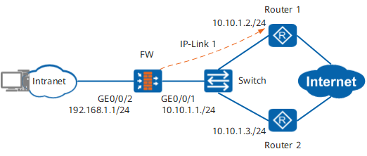
Procedure
- Configure two IP-links to detect the links from FW to router 1 and router 2.
[FW] ip-link check enable
[FW] ip-link name test1
[FW-iplink-test1] destination 10.10.1.2
[FW-iplink-test1] quit
[FW] ip-link name test2
[FW-iplink-test2] destination 10.10.1.3
[FW-iplink-test2] quit
- Install two static routes to reach the Internet and bind them to the two IP-links. Set the preferences of the two links to ensure that the link to router 1 has a higher preference.

This case uses a direct route as an example. If the indirect route is used in the actual application, configure a 32-bit detailed route to the IP-Link probe address to ensure that the IP-Link probe can work normally.
[FW] ip route-static 0.0.0.0 0.0.0.0 10.10.1.2 track ip-link test1
[FW] ip route-static 0.0.0.0 0.0.0.0 10.10.1.3 preference 70 track ip-link test2
Verification
Verify the configuration on the FW as follows:
When the links between the FW and the two routers are both normal, run the display ip-link command. The output resembles:
[FW] display ip-link
Current Total Ip-link Number : 2
Name                            Member   State   Up/Down/Init
test1                           1        up      1  0    0
test2                           1        up      1  0    0
Run the display ip routing-table command, the output shows that the default route to the Internet is the one directed to router 1.
[FW] display ip routing-table
Route Flags: R - relay, D - download to fib
------------------------------------------------------------------------------
Routing Tables: Public
        Destinations : 8        Routes : 8

Destination/Mask    Proto  Pre  Cost     Flags NextHop         Interface
        0.0.0.0/0   Static 60   0          RD  10.10.1.2       GigabitEthernet0/0/1
      127.0.0.0/8   Direct 0    0           D  127.0.0.1       InLoopBack0
      127.0.0.1/32  Direct 0    0           D  127.0.0.1       InLoopBack0
      10.10.1.0/24  Direct 0    0           D  10.10.1.1       GigabitEthernet0/0/1
      10.10.1.1/32  Direct 0    0           D  127.0.0.1       InLoopBack0
    192.168.1.0/24  Direct 0    0           D  192.168.1.1     GigabitEthernet0/0/2
    192.168.1.1/32  Direct 0    0           D  127.0.0.1       InLoopBack0
Run the display ip routing-table verbose command. The output resembles:
[FW] display ip routing-table verbose
Route Flags: R - relay, D - download to fib
------------------------------------------------------------------------------
Routing Tables: Public
        Destinations : 8        Routes : 8

Destination: 0.0.0.0/0
     Protocol: Static          Process ID: 0
   Preference: 60                    Cost: 0
      NextHop: 10.10.1.2        Neighbour: 0.0.0.0
        State: Active Adv Relied        Age: 00h03m29s
          Tag: 0                 Priority: 0
        Label: NULL               QoSInfo: 0x0
   IndirectID: 0x80000004
 RelayNextHop: 0.0.0.0          Interface: GigabitEthernet0/0/1
     TunnelID: 0x0                  Flags: RD

Destination: 0.0.0.0/0
     Protocol: Static          Process ID: 0
   Preference: 70                    Cost: 0
      NextHop: 10.10.1.3        Neighbour: 0.0.0.0
        State: Inactive Adv Relied      Age: 00h00m08s
          Tag: 0                 Priority: 0
        Label: NULL               QoSInfo: 0x0
   IndirectID: 0x80000005
 RelayNextHop: 0.0.0.0          Interface: GigabitEthernet0/0/1
     TunnelID: 0x0                  Flags: R
The output shows that when the two links are normal, the preference value of the route to 10.10.1.2 is 60 (the default preference value). Therefore, the link is in the Active state and is installed in the routing table. The route to 10.10.1.3 has a preference value of 70 and is in the Inactive state. This route is the backup route and is not installed in the routing table.
When the link to router 1 breaks, run the display ip-link command. The output shows that the IP-link to 10.10.1.2 is down.
[FW] display ip-link
Current Total Ip-link Number : 2
Name                            Member   State   Up/Down/Init
test1                           1        down    0  1    0
test2                           1        up      1  0    0
Run the display ip routing-table command, the output shows that the default route to the Internet is the one directed to router 2.
[FW] display ip routing-table
Route Flags: R - relay, D - download to fib
------------------------------------------------------------------------------
Routing Tables: Public
        Destinations : 8        Routes : 8

Destination/Mask    Proto  Pre  Cost     Flags NextHop         Interface
        0.0.0.0/0   Static 70   0          RD  10.10.1.3       GigabitEthernet0/0/1
      127.0.0.0/8   Direct 0    0           D  127.0.0.1       InLoopBack0
      127.0.0.1/32  Direct 0    0           D  127.0.0.1       InLoopBack0
      10.10.1.0/24  Direct 0    0           D  10.10.1.1       GigabitEthernet0/0/1
      10.10.1.1/32  Direct 0    0           D  127.0.0.1       InLoopBack0
    192.168.1.0/24  Direct 0    0           D  192.168.1.1     GigabitEthernet0/0/2
    192.168.1.1/32  Direct 0    0           D  127.0.0.1       InLoopBack0
Run the display ip routing-table verbose command. The output resembles:
[FW] display ip routing-table verbose
Route Flags: R - relay, D - download to fib
------------------------------------------------------------------------------
Routing Tables: Public
        Destinations : 8        Routes : 8

Destination: 0.0.0.0/0
     Protocol: Static          Process ID: 0
   Preference: 70                    Cost: 0
      NextHop: 10.10.1.3        Neighbour: 0.0.0.0
        State: Active Adv Relied      Age: 00h00m08s
          Tag: 0                 Priority: 0
        Label: NULL               QoSInfo: 0x0
   IndirectID: 0x80000004
 RelayNextHop: 0.0.0.0          Interface: GigabitEthernet0/0/1
     TunnelID: 0x0                  Flags: R


Destination: 0.0.0.0/0
     Protocol: Static          Process ID: 0
   Preference: 60                    Cost: 0
      NextHop: 10.10.1.2        Neighbour: 0.0.0.0
        State: Invalid Adv Relied        Age: 00h03m29s
          Tag: 0                 Priority: 0
        Label: NULL               QoSInfo: 0x0
   IndirectID: 0x80000005
 RelayNextHop: 0.0.0.0          Interface: GigabitEthernet0/0/1
     TunnelID: 0x0                  Flags: RD
The output shows that when the link to 10.10.1.2 breaks, the state of IP-link 1 is Down and the route to 10.10.1.2 is set to Invalid. The route to 10.10.1.3, which has a preference value of 70, is set to Active and installed in the routing table.
The outputs show that the configuration is correct.