CLI: Example for Configuring the Interworking Between PBR and IP-Link
This example describes how to configure PBR to select next hops for various packets and balance link traffic. It also describes how to use IP-link for monitoring the reachability of links where the next hops of the packets on policy-based routes reside and dynamically determining the availability of the policy-based routes by IP-link state. When a policy-based route is unavailable, the device can search for standby routes to ensure link continuity.
Networking Requirements
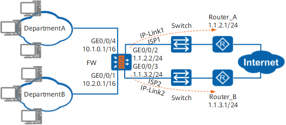
As shown in Figure 1, an enterprise has departments A and B. Departments A and B, acting as service departments, have heavy traffic and require different links for traffic balancing. In addition, the departments require high stability and continuity.
To meet their requirements, the enterprise applies for two links that access the Internet, namely, ISP1 and ISP2 to balance link traffic. The two links are mutually backed up to ensure link continuity.
The requirements are as follows:
- Department A resides on network segment 10.1.0.0/16 and its packets for accessing the Internet pass through link ISP1 in normal cases.
- Department B resides on network segment 10.2.0.0/16 and its packets for accessing the Internet pass through link ISP2 in normal cases.
- The links of departments A and B are mutually backed up. When the link (active link) of a department is faulty, traffic is switched to the link (standby link) of another department.
Configuration Roadmap

This example describes only PBR-related configurations, but not configurations (such as NAT and route reachability among Router_A, Router_B, and FW) required by the FW for providing Internet access services.
The roadmap for configuring PBR to interwork with IP-link is as follows:
To balance traffic on different links, configure source IP address-based PBR, so that packets for accessing the Internet from department A pass through ISP1 and packets for accessing the Internet from department B pass through ISP2.
- To ensure the continuity and mutual standby of links at which departments A and B reside, do as follows:
- Configure PBR to interwork with IP-link. IP-link monitors the reachability of the active links of departments A and B. When the active links are faulty, PBR becomes invalid. The device searches for standby routes to ensure service continuity.
- Configure static routes from department A to link ISP2 and from department B to link ISP1 as the standby routes of departments A and B. Moreover, configure static routes to interwork with IP-link. IP-link monitors the reachability of the standby links of departments A and B.
Procedure
- Configure IP-link.
To ensure interworking between PBR and IP-link, the destination IP address detected by IP-link must be consistent with the setting of the next hop of packets.
# Enable IP-link.
[FW] ip-link check enable# Create IP-link 1 for detecting link reachability from the FW to destination address 1.1.2.1.
[FW] ip-link name test1
[FW-iplink-test1] destination 1.1.2.1
[FW-iplink-test1] quit
# Create IP-link 2 for detecting link reachability from the FW to destination address 1.1.3.1.
[FW] ip-link name test2
[FW-iplink-test2] destination 1.1.3.1
[FW-iplink-test2] quit
- Configure policy-based routing and associate it with IP-link.
# Configure rule A_1, so that packets sent from 10.1.0.0/16 to 10.2.0.0/16 are not pbr.
[FW] policy-based-route
[FW-policy-pbr] rule name A_1
[FW-policy-pbr-rule-A_1] ingress-interface GigabitEthernet 0/0/4
[FW-policy-pbr-rule-A_1] source-address 10.1.0.0 16
[FW-policy-pbr-rule-A_1] destination-address 10.2.0.0 16
[FW-policy-pbr-rule-A_1] action no-pbr
[FW-policy-pbr-rule-A_1] quit
# Configure rule A_2, so that packets sent from 10.1.0.0/16 are sent to next-hop 1.1.2.1.
[FW-policy-pbr] rule name A_2
[FW-policy-pbr-rule-A_2] ingress-interface GigabitEthernet 0/0/4
[FW-policy-pbr-rule-A_2] source-address 10.1.0.0 16
[FW-policy-pbr-rule-A_2] action pbr next-hop 1.1.2.1
Configure rule A_2 to interwork with IP-link 1
[FW-policy-pbr-rule-A_2] track ip-link test1
[FW-policy-pbr-rule-A_2] quit
# Configure rule B_1, so that packets sent from 10.2.0.0/16 to 10.1.0.0/16 are not pbr.
[FW-policy-pbr] rule name B_1
[FW-policy-pbr-rule-B_1] ingress-interface GigabitEthernet 0/0/1
[FW-policy-pbr-rule-B_1] source-address 10.2.0.0 16
[FW-policy-pbr-rule-B_1] destination-address 10.1.0.0 16
[FW-policy-pbr-rule-B_1] action no-pbr
[FW-policy-pbr-rule-B_1] quit
# Configure rule B_2, so that packets sent from 10.2.0.0/16 are sent to next-hop 1.1.3.1.
[FW-policy-pbr] rule name B_2
[FW-policy-pbr-rule-B_2] ingress-interface GigabitEthernet 0/0/1
[FW-policy-pbr-rule-B_2] source-address 10.2.0.0 16
[FW-policy-pbr-rule-B_2] action pbr next-hop 1.1.3.1
Configure rule B_2 to interwork with IP-link 2
[FW-policy-pbr-rule-B_2] track ip-link test2
[FW-policy-pbr-rule-B_2] quit
[FW-policy-pbr]quit
- Configure default routes and associate them with IP-link.
# Configure the default route, set the next hop to 1.1.2.1/24, and associate the route with IP-link 1.
[FW] ip route-static 0.0.0.0 0.0.0.0 1.1.2.1 track ip-link test1# Configure the default route, set the next hop to 1.1.3.1/24, and associate the route with IP-link 2.
[FW] ip route-static 0.0.0.0 0.0.0.0 1.1.3.1 track ip-link test2
Verification
When active links are reachable, packets for accessing the Internet from department A are forwarded by the FWto ISP1, and packets for accessing the Internet from department B are forwarded by the FW to ISP2.
# Run the display ip-link command. You can view that the IP-links are Up.
[FW] display ip-link
Current Total Ip-link Number : 2
Name                            Member   State   Up/Down/Init
test1                           1        up      1  0    0
test2                           1        up      1  0    0
# Run the ping 1.1.2.1 command in department A. The ping attempt is successful. Then run the ping 1.1.3.1 command. The pinging attempt is unsuccessful.
C:\Documents and Settings\DepartA>ping 1.1.2.1

Pinging 1.1.2.1 with 32 bytes of data:

Reply from 1.1.2.1: bytes=32 time=9ms TTL=254
Reply from 1.1.2.1: bytes=32 time=2ms TTL=254
Reply from 1.1.2.1: bytes=32 time=2ms TTL=254
Reply from 1.1.2.1: bytes=32 time=5ms TTL=254

Ping statistics for 1.1.2.1:
    Packets: Sent = 4, Received = 4, Lost = 0 (0% loss),
Approximate round trip times in milli-seconds:
    Minimum = 2ms, Maximum = 9ms, Average = 4ms

C:\Documents and Settings\DepartA>ping 1.1.3.1

Pinging 1.1.3.1 with 32 bytes of data:

Request timed out.
Request timed out.
Request timed out.
Request timed out.

Ping statistics for 1.1.3.1:
    Packets: Sent = 4, Received = 0, Lost = 4 (100% loss),
# Run the ping 1.1.3.1 command in department B. The pinging attempt is successful. Then run the ping 1.1.2.1 command. The pinging attempt is unsuccessful.
C:\Documents and Settings\DepartB>ping 1.1.3.1

Pinging 1.1.3.1 with 32 bytes of data:

Reply from 1.1.3.1: bytes=32 time=2ms TTL=254
Reply from 1.1.3.1: bytes=32 time=1ms TTL=254
Reply from 1.1.3.1: bytes=32 time=1ms TTL=254
Reply from 1.1.3.1: bytes=32 time=2ms TTL=254

Ping statistics for 1.1.3.1:
    Packets: Sent = 4, Received = 4, Lost = 0 (0% loss),
Approximate round trip times in milli-seconds:
    Minimum = 1ms, Maximum = 2ms, Average = 1ms

C:\Documents and Settings\DepartB>ping 1.1.2.1

Pinging 1.1.2.1 with 32 bytes of data:

Request timed out.
Request timed out.
Request timed out.
Request timed out.

Ping statistics for 1.1.2.1:
    Packets: Sent = 4, Received = 0, Lost = 4 (100% loss),
When the active link is faulty, the FW searches for the standby route and forwards the packets of departments to the corresponding standby link. Active link ISP1 of department A is used as an example for explanation.
# Run the display ip-link command. The IP-link where department A resides is Down.
[FW] display ip-link
Current Total Ip-link Number : 2
Name                            Member   State   Up/Down/Init
test1                           1        down    0  1    0
test2                           1        up      1  0    0
# Run the ping 1.1.2.1 command in department A. The pinging attempt is unsuccessful. Then run the ping 1.1.3.1 command. The pinging attempt is successful.
C:\Documents and Settings\DepartA>ping 1.1.3.1

Pinging 1.1.3.1 with 32 bytes of data:

Reply from 1.1.3.1: bytes=32 time=2ms TTL=254
Reply from 1.1.3.1: bytes=32 time=1ms TTL=254
Reply from 1.1.3.1: bytes=32 time=1ms TTL=254
Reply from 1.1.3.1: bytes=32 time=2ms TTL=254

Ping statistics for 1.1.3.1:
    Packets: Sent = 4, Received = 4, Lost = 0 (0% loss),
Approximate round trip times in milli-seconds:
    Minimum = 1ms, Maximum = 2ms, Average = 1ms

C:\Documents and Settings\DepartA>ping 1.1.2.1

Pinging 1.1.2.1 with 32 bytes of data:

Request timed out.
Request timed out.
Request timed out.
Request timed out.

Ping statistics for 1.1.2.1:
    Packets: Sent = 4, Received = 0, Lost = 4 (100% loss),
When active links restore to normal, the FW forwards all packets to the active links. Active link ISP1 of department A is used as an example.
# Run the display ip-link command. Both IP-links of department A are Up.
[FW] display ip-link
Current Total Ip-link Number : 2
Name                            Member   State   Up/Down/Init
test1                           1        up      1  0    0
test2                           1        up      1  0    0
# Run the ping 1.1.2.1 command in department A. The pinging attempt is successful. Then run the ping 1.1.3.1 command. The pinging attempt is unsuccessful.
C:\Documents and Settings\DepartA>ping 1.1.2.1

Pinging 1.1.2.1 with 32 bytes of data:

Reply from 1.1.2.1: bytes=32 time=2ms TTL=254
Reply from 1.1.2.1: bytes=32 time=1ms TTL=254
Reply from 1.1.2.1: bytes=32 time=1ms TTL=254
Reply from 1.1.2.1: bytes=32 time=2ms TTL=254

Ping statistics for 1.1.2.1:
    Packets: Sent = 4, Received = 4, Lost = 0 (0% loss),
Approximate round trip times in milli-seconds:
    Minimum = 1ms, Maximum = 2ms, Average = 1ms

C:\Documents and Settings\DepartA>ping 1.1.3.1

Pinging 1.1.3.1 with 32 bytes of data:

Request timed out.
Request timed out.
Request timed out.
Request timed out.

Ping statistics for 1.1.3.1:
    Packets: Sent = 4, Received = 0, Lost = 4 (100% loss),
The mutual access of departments A and B is successful. The pinging attempt from department A to B is used as an example.
C:\Documents and Settings\DepartA>ping 10.2.0.111

Pinging 10.2.0.111 with 32 bytes of data:

Reply from 10.2.0.111: bytes=32 time=2ms TTL=127
Reply from 10.2.0.111: bytes=32 time=1ms TTL=127
Reply from 10.2.0.111: bytes=32 time=1ms TTL=127
Reply from 10.2.0.111: bytes=32 time=2ms TTL=127

Ping statistics for 10.2.0.111:
    Packets: Sent = 4, Received = 4, Lost = 0 (0% loss),
Approximate round trip times in milli-seconds:
    Minimum = 1ms, Maximum = 2ms, Average = 1ms
Configuration Scripts
Configuration scripts of FW
#
sysname FW
#
ip-link check enable
ip-link name test1
 destination 1.1.2.1
ip-link name test2
 destination 1.1.3.1
#
interface GigabitEthernet0/0/1
 ip address 10.2.0.1 255.255.0.0
#
interface GigabitEthernet0/0/2
 ip address 1.1.2.2 255.255.255.0
#
interface GigabitEthernet0/0/3
 ip address 1.1.3.2 255.255.255.0
#
interface GigabitEthernet0/0/4
 ip address 10.1.0.1 255.255.0.0
#
 ip route-static 0.0.0.0 0.0.0.0 1.1.2.1 track ip-link test1
 ip route-static 0.0.0.0 0.0.0.0 1.1.3.1 track ip-link test2
#
policy-based-route
 rule name A_1
  ingress-interface GigabitEthernet0/0/4
  source-address 10.1.0.0 16
  destination-address 10.2.0.0 16
  action no-pbr
 rule name A_2
  ingress-interface GigabitEthernet0/0/4
  source-address 10.1.0.0 16
  track ip-link test1
  action pbr next-hop 1.1.2.1
 rule name B_1
  ingress-interface GigabitEthernet0/0/1
  source-address 10.2.0.0 16
  destination-address 10.1.0.0 16
  action no-pbr
 rule name B_2
  ingress-interface GigabitEthernet0/0/1
  source-address 10.2.0.0 16
  track ip-link test2
  action pbr next-hop 1.1.3.1
#
return