Configuring an IPv4 over IPv6 Tunnel Using the CLI
An IPv4 over IPv6 tunnel encapsulates IPv4 data packets, so that these encapsulated packets can be transmitted on an IPv6 network.
Prerequisites
- IPv6 packet forwarding is enabled globally.
- An IPv6 address is configured for the interface connecting to an IPv6 network, the interface is Up, and the IPv6 address is routable.
Context
Application Scenario
An IPv4 over IPv6 tunnel is configured between two border devices.
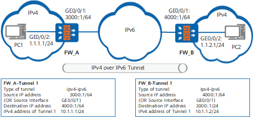
As shown in Figure 1, both FW_A and FW_B support the dual stack and connect to IPv6 network and IPv4 networks. The IPv4 over IPv6 tunnel connects to two different IPv4 networks, which enables the PCs or devices on different IPv4 networks to communicate.
Tunnel Route
After you configure an IPv4 over IPv6 tunnel, ensure that the source and destination of the tunnel have a route to each other to implement normal packet forwarding. The routes can be either static or dynamic.
To configure a static route, set the destination address of the route to the IPv4 address of the tunnel interface on the IPv6 network and the outbound interface to the local tunnel interface.
- To configure a dynamic route, enable dynamic routing protocols on the tunnel interfaces and interfaces connected to the IPv4 networks.

For details on route configurations, see "IP Routing".
Procedure
- Access the system view.
- Create a tunnel interface and access the tunnel interface view.
interface tunnel interface-number
- Set the tunnel type to IPv4 over IPv6.
tunnel-protocol ipv4-ipv6
- Set a source IPv6 address or interface for the tunnel.
source { source-ipv6-address | interface-type interface-number }
You can set the source address of a manual tunnel to the IPv6 address of the interface connecting to the IPv6 network or configure this interface as the source interface.
Moreover, you can specify a physical interface or a logical interface such as the loopback interface as the source interface.
- Set a destination IPv6 address for the tunnel.
destination ipv4-address
The destination address is the source address of the tunnel on the peer device. As shown in Figure 1, the source IP address of tunnel on the FW_A is 4000::1/64 and that on FW_B is 3000::1/64.
- Set an IPv4 address for the tunnel interface.
ip address ip-address { mask | mask-length } [ sub ]
- Optional: Perform other IPv4 over IPv6 tunnel configurations.
Run the ipv4-ipv6 encapsulation-limit encapsulation-limit command to set a maximum number of times that IPv6 encapsulation can be performed.
By default, a maximum of four times of IPv6 encapsulation can be performed on embedded tunnel nodes.
Run the tunnel ipv4-ipv6 flow-label label-value command to set a flow label value.
By default, the flow label value is 0.
Run the tunnel ipv4-ipv6 hop-limit hop-limit command to set a hop-limit value.
By default, the hop-limit value is 64.
Run the tunnel ipv4-ipv6 traffic-class { original | class-value } command to set a traffic class.
The default traffic class is 0.
Example
FW_A and FW_B are border devices between IPv6 and IPv4 networks. The IPv6 address of GE0/0/1 that connects FW_A to the IPv6 network is 3000::1/64, and the IPv4 address of GE0/0/2 that connects FW_A to the IPv4 network is 1.1.1.1/24. The IPv6 address of GE0/0/1 that connects FW_B to the IPv6 network is 4000::1/64, and the IPv4 address of GE0/0/2 that connects FW_B to the IPv4 network is 1.1.2.1/24. An IPv4 over IPv6 tunnel is established between FW_A and FW_B.
# On FW_A, configure an encapsulation type, a source address, and a destination address for the tunnel and configure an IPv4 address for the tunnel interface.
<FW> system-view
[FW] sysname FW_A
[FW_A]ipv6
[FW_A] interface tunnel 1
[FW_A-Tunnel1] tunnel-protocol ipv4-ipv6
[FW_A-Tunnel1] source 3000::1
[FW_A-Tunnel1] destination 4000::1
[FW_A-Tunnel1] ip address 10.1.1.1 24
# Configure a route from FW_A to the IPv4 network connected to FW_B.
[FW_A] ip route-static 1.1.2.0 255.255.255.0 tunnel 1
# On FW_B, configure an encapsulation type, a source address, and a destination address for tunnel and configure an IPv4 address for the tunnel interface.
<FW> system-view
[FW] sysname FW_B
[FW_B]ipv6
[FW_B] interface tunnel 1
[FW_B-Tunnel1] tunnel-protocol ipv4-ipv6
[FW_B-Tunnel1] source 4000::1
[FW_B-Tunnel1] destination 3000::1
[FW_B-Tunnel1] ip address 10.1.1.2 24
# Configure a route from FW_B to the IPv4 network connected to FW_A.
[FW_B] ip route-static 1.1.1.0 255.255.255.0 tunnel 1