Mechanism of L2TP VPN in the Client-Initiated Scenario
This section describes the mechanism of L2TP VPN in the client-initiated scenario in terms of tunnel negotiations, packet encapsulation, and security policies.
Tunnel Negotiation
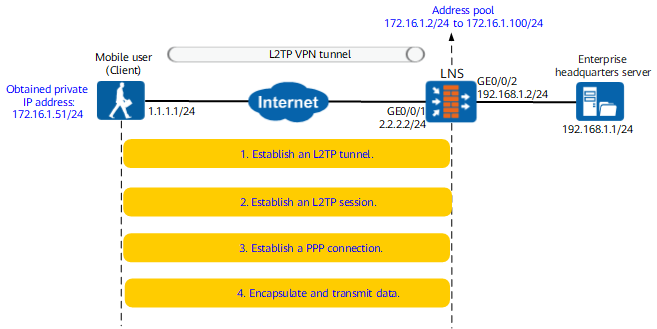
- The mobile user establishes an L2TP VPN tunnel with the LNS.
Packet Exchange Procedure
Packet Content
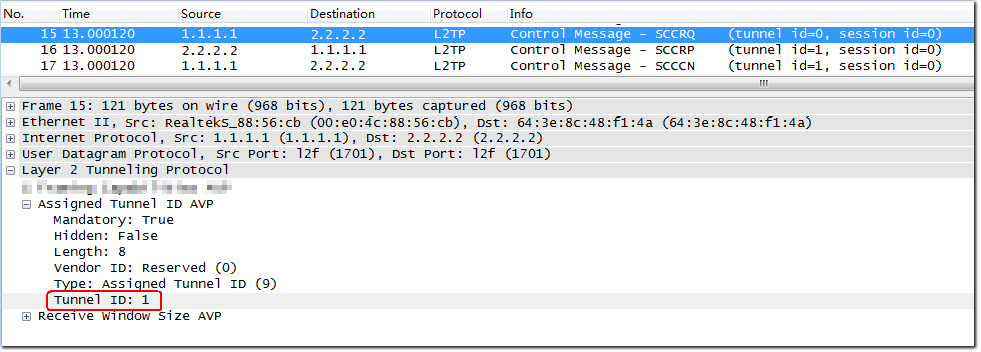
Client: sends an SCCRQ packet to notify the LNS of the tunnel ID (1). The client uses the initial tunnel ID (0) to send an SCCRQ packet.
In L2TP VPN, an LNS can establish multiple tunnels simultaneously to transmit different user services. The LNS negotiates the IDs for tunnels to be established to distinguish between the tunnels.
L2TP packets are transmitted using UDP. When sending an SCCRQ packet, the client selects an idle interface as the source interface to send the packet to interface 1701 of the LNS. After receiving the packet, the LNS uses interface 1701 to send a response packet to the specified interface of the client. The interfaces at both sides are fixed until the tunnel is disconnected.
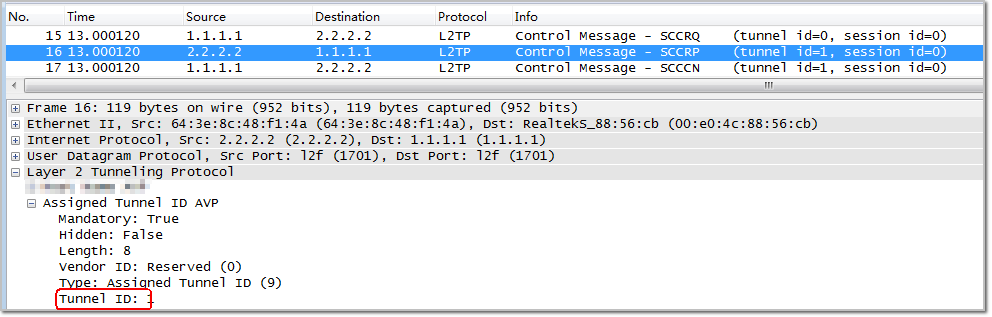
LNS: sends an SCCRP packet to notify the client of the tunnel ID (1).
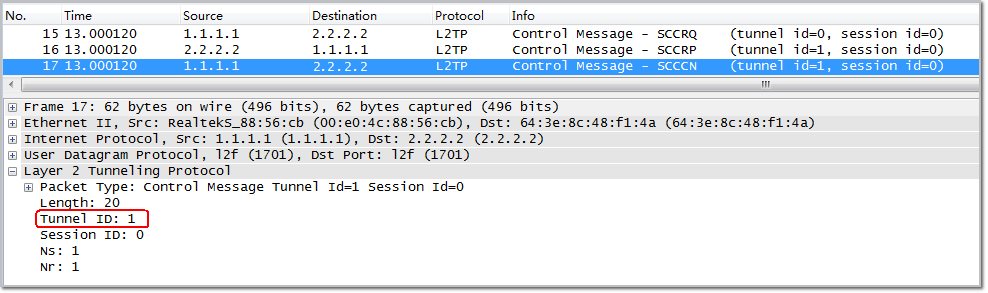
Client: sends an SCCCN packet.
So far, the two devices have negotiated the tunnel ID to establish an L2TP VPN tunnel.
- The mobile user establishes an L2TP VPN session with the LNS.
In Step 3, the mobile user establishes a PPP connection with the LNS. The L2TP session is used to record and manage the status of the PPP connection. Therefore, before establishing a PPP connection, the client and LNS need to negotiate an L2TP session.
Packet Exchange Procedure
Packet Content
Client: sends an ICRQ packet to notify the LNS of the session ID (81).
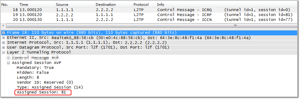
LNS: sends an ICRP packet to notify the client of the session ID (77).
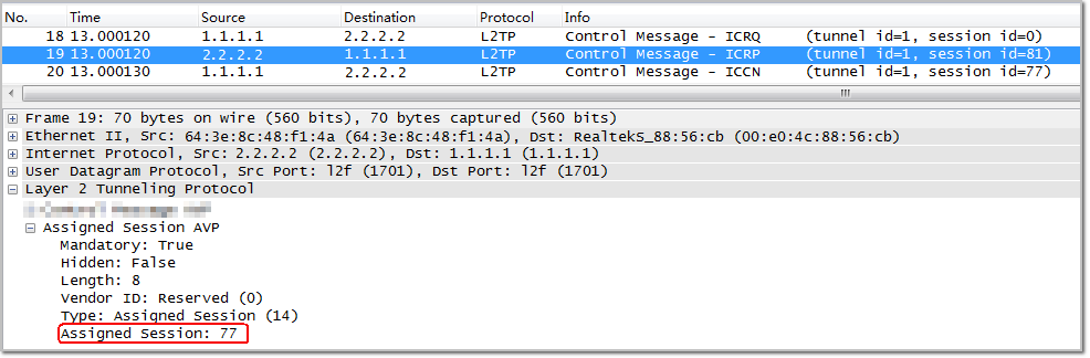
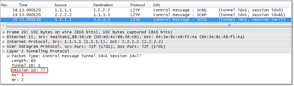
Client: sends an ICCN packet.
So far, the two devices have negotiated the session ID to establish an L2TP session.
- The mobile user establishes a PPP connection with the LNS.
The mobile user establishes a PPP connection with the LNS to obtain an intranet IP address from the LNS.
Packet Exchange Procedure
Packet Content
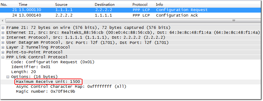
Client: sends an LCP Request packet to negotiate link-layer parameters. For example, as shown in the figure at the right side, the negotiated MRU is 1500.
The LNS returns an LCP ACK packet to the client.
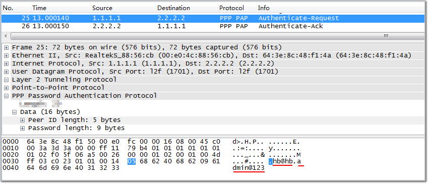
Client: sends a PAP Request packet to request the LNS to perform identity authentication. As shown in the figure at the right side, the PAP packet carries user name hb@hb and password admin@123. The LNS returns a PAP ACK packet carrying the authentication result.
If the mobile user uses CHAP authentication, the authentication process is little different. For details, see section PPP CHAP.
NOTE:An L2TP VPN tunnel does not have the data encapsulation function. To prevent user data theft, you are advised to use the IPSec technology to provide the data encryption function for L2TP VPN.
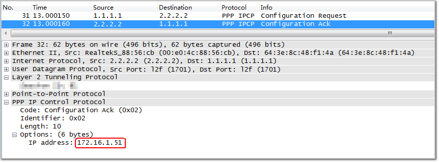
Client: After identity authentication succeeds, the client sends an IPCP Request packet to request the LNS to assign an intranet IP address.
The LNS sends an IPCP ACK packet to the client. The packet carries the intranet IP address allocated to the client. So far, the PPP connection has been established. As shown in the figure on the right side, the intranet address assigned by the LNS to the client is 172.16.1.51.
- The mobile user sends service packets to access a server on the enterprise headquarters.
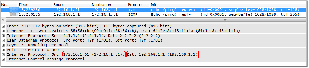
As shown in the following figure, the mobile user uses intranet address 172.16.1.51 to access intranet server 192.168.1.1. The packet from the user is encapsulated and decapsulated and reaches the intranet server. For details on packet encapsulation, see Packet Encapsulation.
Packet Encapsulation
- The mobile user sends a service packet to a server on the enterprise headquarters.
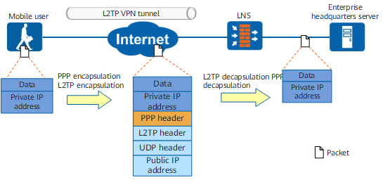
The service packet is encapsulated with the PPP and L2TP headers and is sent by the PC of the mobile user to the LNS based on the local route.
- After receiving the packet, the LNS authenticates the user, decapsulates the packet, removes the PPP header, L2TP header, UDP header and outer IP header, to restore the original packet, and then forwards the packet to the server on the enterprise headquarters based on the intranet route.
- After the receiving the packet, the server on the enterprise headquarters returns a response packet to the mobile user.
Security Policy
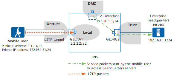
- Figure 3 shows the security zones that packets pass through on the LNS.When a mobile employee accesses an intranet server on the enterprise headquarters, the packets that pass through the LNS are classified into two types, and the security policy processes the two types of packets as follows:
- L2TP packets exchanged by the PC of the mobile employee and the LNS
The L2TP packets include the L2TP negotiation packets exchanged between the PC of the mobile employee and LNS to establish a tunnel and the pre-decapsulated service packets sent by the mobile employee to access the intranet server of the enterprise headquarters. The L2TP packets are transmitted from the Untrust zone to the Local zone.
- Service packets sent by the mobile employee to the server on the enterprise headquarters
The VT interface of the LNS decapsulates the service packets sent by the mobile employee to the server on the enterprise headquarters. The packets are transmitted from the DMZ to the Trust zone. The VT interface on the LNS resides in the DMZ, and the interface connecting the LNS to the intranet of the enterprise headquarters resides in the Trust zone.
- L2TP packets exchanged by the PC of the mobile employee and the LNS
Traffic Direction |
Device |
Source Zone |
Destination Zone |
Source Address |
Destination Address |
Application |
|---|---|---|---|---|---|---|
Packet sent by the mobile employee to access the server on the enterprise headquarters |
LNS |
Untrust |
Local |
Any |
2.2.2.2/32 |
L2TP |
DMZ |
Trust |
172.16.1.2 to 172.16.1.100/24 (addresses in the address pool) |
192.168.1.0/24 |
* |
||
Packet sent by the server on the enterprise headquarters to the PC of the mobile user |
LNS |
Trust |
DMZ |
192.168.1.0/24 |
172.16.1.2 to 172.16.1.100/24 (addresses in the address pool) |
* |