CLI: Example for Configuring L2TP VPN (RADIUS Server Authentication) in the NAS-Initiated Scenario
This section provides an example for configuring L2TP VPN in the NAS-initiated scenario. In the scenario, PPPoE dialup users access intranet resources at the headquarters through the L2TP VPN tunnel between the NAS and LNS.
Networking Requirements
As shown in Figure 1, a dialup user accesses the Internet through PPPoE. The NAS is the PPPoE access server provided by the provider, and the LNS is the egress gateway of the enterprise. The device of the dialup user needs to establish a PPPoE connection with the NAS so that the user can access the enterprise intranet through the L2TP VPN tunnel between the NAS and LNS.
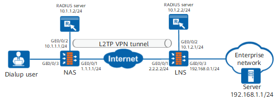
Data Planning
Item |
Data |
|
|---|---|---|
NAS |
Interface |
Interface ID: GigabitEthernet 0/0/1 IP address: 1.1.1.1/24 Security zone: Untrust Interface ID: GigabitEthernet 0/0/2 IP address: 10.1.1.1/24 Security zone: DMZ Interface ID: GigabitEthernet 0/0/3 IP address: 10.1.3.1/24 Security zone: Trust |
L2TP configuration |
User name: user0001 Password: Password123 Local tunnel name: NAS Tunnel authentication password: Hello123 LNS server address: 2.2.2.2 |
|
LNS |
Interface |
Interface ID: GigabitEthernet 0/0/1 IP address: 2.2.2.2/24 Security zone: Untrust Interface ID: GigabitEthernet 0/0/2 IP address: 10.1.2.1/24 Security zone: DMZ Interface ID: GigabitEthernet 0/0/3 IP address: 192.168.0.1/24 Security zone: Trust |
L2TP configuration |
Peer tunnel name: NAS Tunnel authentication password: Hello123 User name: user0001 Password: Password123 User address pool: 10.2.1.2/24 to 10.2.1.100/24 |
|
Procedure
- Configure the NAS.
- Configure the authentication domain and user information.
- Set parameters for interconnecting with the RADIUS server.
- When RADIUS authentication is used, configure an authentication template. The authentication mode is RADIUS authentication.
- Configure the authentication domain and reference the RADIUS server template.
- Configure the authentication domain and user information.
- Configure the LNS.
- Configure L2TP access users and an authentication policy on the LNS.
- Set parameters for interconnecting with the RADIUS server.
- Configure RADIUS authentication for user identity authentication.
- Configure an address pool.
If the actual address pool addresses and headquarters addresses reside on the same network segment, you must enable the proxy ARP function on the LNS interface connecting to the headquarters to ensure that the LNS can respond to the ARP requests from the servers at the headquarters.
[LNS] ip pool pool
[LNS-ip-pool-pool] section 1 10.2.1.2 10.2.1.100
[LNS-ip-pool-pool] quit
- Configure the service scheme used by access users.
- Configure the authentication domain and reference the RADIUS server template and authentication scheme.
- Configure L2TP access users and an authentication policy on the LNS.
- Configure a PPPoE connection on the PC of an individual user.

Verification
- When a dialup user goes online, run the display l2tp tunnel command on the NAS and LNS to display established L2TP tunnels. The command output on the LNS is used as an example.
[LNS] display l2tp tunnel
L2TP::Total Tunnel: 1

 LocalTID RemoteTID RemoteAddress    Port   Sessions RemoteName  VpnInstance
 ------------------------------------------------------------------------------
 1        1         10.2.1.3         1701     1        NAS
 ------------------------------------------------------------------------------
  Total 1, 1 printed
Run the display l2tp session command to display established sessions. The command output on the LNS is used as an example.
[LNS] display l2tp session
L2TP::Total Session: 1

  LocalSID  RemoteSID  LocalTID   RemoteTID  UserID  UserName    VpnInstance
 ------------------------------------------------------------------------------
  55        3          1          1                  user0001
 ------------------------------------------------------------------------------
  Total 1, 1 printed
Configuration Scripts
Configuration script of the NAS
#
 sysname NAS
#
 l2tp enable
 l2tp domain suffix-separator @
#
radius-server template radius_nas
 radius-server shared-key cipher %@%@Bhr,Ij`8>9P)^"+#m\QFhif%%@%@
 radius-server authentication 10.1.1.2 1812
#
aaa
 authentication-scheme scheme_radius
  authentication-mode radius
#
 domain default
  service-type l2tp
  authentication-scheme scheme_radius
  radius-server radius_nas
#
l2tp-group 1
 tunnel name NAS
 start l2tp ip 2.2.2.2 domain default
 tunnel authentication
 tunnel password cipher %$%$^-K[,X+KrHiUg"3=DoLNy:\g%$%$
#
interface Virtual-Template1
 ip address 172.16.1.1 24
 ppp authentication-mode chap
#
interface GigabitEthernet0/0/1
 ip address 1.1.1.1 255.255.255.0
#
interface GigabitEthernet0/0/2
 ip address 10.1.1.1 255.255.255.0
#
interface GigabitEthernet0/0/3
 ip address 10.1.3.1 255.255.255.0
 pppoe-server bind virtual-template 1
#
firewall zone trust
 add interface GigabitEthernet0/0/3
#
firewall zone dmz
 add interface GigabitEthernet0/0/2
  add interface Virtual-Template1
#
firewall zone untrust
 add interface GigabitEthernet0/0/1
#
 ip route-static 0.0.0.0 0.0.0.0 1.1.1.2
#
security-policy
  rule name rule name l2tp_lu
    source-zone local
    destination-zone untrust
    source-address 1.1.1.1 24
    destination-address 2.2.2.2 24
    action permit
  rule name radius_ld
    source-zone local
    destination-zone dmz
    source-address 10.1.1.1 24
    destination-address 10.1.1.2 24
    action permit
Configuration script of the LNS
#
 sysname LNS
#
 l2tp enable
 l2tp domain suffix-separator @
#
radius-server template radius_lns
 radius-server shared-key cipher %@%@Bhr,Ij`8>9P)^"+#m\QFhif%%@%@
 radius-server authentication 10.1.2.2 1812
#
ip pool pool
 section 1 10.2.1.2 10.2.1.100
#
aaa
 authentication-scheme scheme_radius
  authentication-mode radius
#
 service-scheme l2tp
  ip-pool pool
#
 domain default
  service-type l2tp
  authentication-scheme scheme_radius
  radius-server radius_lns
#
l2tp-group 2
 allow l2tp virtual-template 1 remote NAS
 tunnel password cipher %$%$^-K[,X+KrHiUg"3=DoLNy:\g%$%$
#
interface Virtual-Template1
 ip address 10.2.1.1 24
 ppp authentication-mode chap
 remote service-scheme l2tp
#
interface GigabitEthernet0/0/1
 ip address 2.2.2.2 255.255.255.0
#
interface GigabitEthernet0/0/2
 ip address 10.1.2.1 255.255.255.0
#
interface GigabitEthernet0/0/3
 ip address 192.168.0.1 24
#
firewall zone trust
 add interface GigabitEthernet0/0/3
#
firewall zone dmz
 add interface GigabitEthernet0/0/2
 add interface Virtual-Template1
#
firewall zone untrust
 add interface GigabitEthernet0/0/1
#
 ip route-static 0.0.0.0 0.0.0.0 2.2.2.1
#
security-policy
  rule name service_td
    source-zone trust
    destination-zone dmz
    source-address 192.168.1.0 mask 255.255.255.0
    destination-address 10.2.1.0 mask 255.255.255.0
    action permit
  rule name service_dt
    source-zone dmz
    destination-zone trust
    source-address 10.2.1.0 mask 255.255.255.0
    destination-address 192.168.1.0 mask 255.255.255.0
    action permit
  rule name l2tp_ul
    source-zone untrust
    destination-zone local
    source-address 1.1.1.0 mask 255.255.255.0
    destination-address 2.2.2.0 mask 255.255.255.0
    action permit
  rule name rule name radius_ld
    source-zone local
    destination-zone dmz
    source-address 10.1.2.1 mask 255.255.255.0
    destination-address 10.1.2.2 mask 255.255.255.0
    action permit