< Home

Configuring the NAS

This section describes the methods and precautions for configuring the NAS.

Context

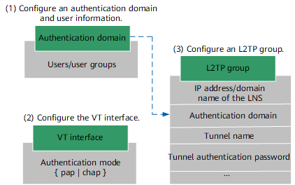
Figure 1 shows the procedures for configuring L2TP VPN on the NAS and their referencing relationships, which helps you better understand and complete service configuration.

This figure provides only critical configuration procedures and their referencing relationships, not all procedures.

Figure 1 Flowchart for configuring L2TP VPN on the NAS

Procedure

  1. Configure the authentication domain and user information.
    1. Create an authentication domain.

      1. Access the AAA view from the system view.

        aaa

      2. Create an authentication domain.

        domain domain-name

        service-type l2tp

        In this section, the authentication domain uses local authentication (the system uses local authentication by default). For information on the authentication domain that uses a third-party server for authentication, see the corresponding Configuring an L2TP VPN in a Virtual System.

    2. Configure users and user groups.

      1. Create a user group in the system view and access the view of the user group.

        user-manage group group-name

      2. Create a user in the system view and access the view of the user.

        user-manage user user-name [ domain domain-name ]

        After an authentication domain is specified, users must enter their user names in the "login-name@authentication-domain-name" format for login. For example, user1@test indicates that user1 belongs to authentication domain test. If no authentication domain is specified, users belong to the default authentication domain.

        In this step a login name (account) is created, namely, the name used for authentication. The login name in domain must be unique.

      3. Configure a user password.

        password password

      4. Configure the user group to which the user belongs.

        parent-group parent-group-name

  2. Configure VT interfaces.
    1. Create a VT interface and access the view of the VT interface.

      interface virtual-template virtual-template-number

      When L2TP VPN is configured on a virtual system, the VT interface cannot be directly configured on the virtual system. The VT interface must be configured through resource binding. Specifically, after a VT interface is configured on the root system, the virtual system administrator uses the assign interface command to bind the configured VT interface to the virtual system.

    2. Configure an IP address for the VT interface.

      ip address ip-address mask

      The IP address of the VT interface cannot be used for packet encapsulation. Only one valid IP address needs to be specified for the VT interface and cannot be conflict with the IP addresses of other services or interfaces.

    3. Configure an authentication mode for a dialup user.

      ppp authentication-mode { chap | eap | pap } *

      When a dialup user establishes a PPPoE connection with the NAS, they will perform LCP negotiation. If multiple authentication modes are configured on the NAS, the NAS will prefer CHAP authentication. If the other party does not support CHAP authentication, the NAS will use PAP authentication. If the other party does not support the two authentication modes, the LCP negotiation fails.

      The device does not support local EAP authentication and needs to interwork with the RADIUS server to implement EAP authentication.

      PAP is not a secure protocol. Therefore, CHAP is recommended. When an AD server is used to authenticate L2TP access users, only PAP authentication can be used.

    4. Bind the VT interface to the physical interface connecting the NAS to the dialup user.

      1. Access the view of the physical interface connecting the NAS to the dialup user.

        interface interface-type interface-number

      2. Bind the VT interface and the physical interface.

        pppoe-server bind virtual-template virtual-template-number

    5. Assign the VT interface to a security zone.

      firewall zone [ name ] zone-name

      add interface virtual-template virtual-template-number

      The VT interface can be assigned to any security zone. The security policy on the NAS is not affected by the security zone where the VT interface resides.

  3. Configure an L2TP group.
    1. Enable L2TP in the system view.

      l2tp enable

    2. Create L2TP group and enter the L2TP group view.

      l2tp-group

    3. Configure LNS addresses.

      start l2tp { lns-domain domain-name | ip ip-address &<1-5> } domain domain-name [ vpn-instance vpn-instance-name ]

      Backup LNS addresses can be configured on the NAS. A maximum of five LNS addresses can be configured on the NAS. Specifically, an NAS can establish connections with a maximum of five LNSs. Normally, the NAS initiates L2TP connection requests to the LNSs based on the LNS configuration sequence until an LNS accepts the connection request.

      In the scenario where one NAS corresponds to multiple backup LNSs and uses RADIUS authentication, if the LNS IP address delivered by the RADIUS server is unreachable, no backup LNS IP address will be used to establish an L2TP tunnel.

    4. Optional: Configure a tunnel source interface.

      tunnel source loopback interface-number

      By default, the NAS uses the IP address of the interface that initiates the L2TP VPN tunnel negotiation as the source address.

      If no IP address is configured for the tunnel source interface, the IP address of the interface used to establish the L2TP VPN tunnel will be used as the source address. Only a loopback interface can be specified as a tunnel source interface.

    5. Optional: Configure the local tunnel name.

      tunnel name tunnel-name

      The tunnel name is a tunnel ID. When the NAS negotiates an L2TP VPN tunnel with the LNS, the SCCRQ packet sent by the NAS will carry the tunnel name. The LNS will use the configured peer tunnel name to verify the local tunnel name sent from the NAS. If the verification succeeds, the L2TP VPN negotiation can continue. If the verification fails, the L2TP VPN negotiation stops, and the tunnel fails to be established. The local tunnel name on the NAS must be the peer tunnel name configured for the corresponding the L2TP group on the LNS. If tunnel-name is not set, the NAS uses the device name as the local tunnel name.

    6. Optional: Enable the tunnel password authentication function.

      tunnel authentication

      Enabling the function enhances the tunnel security. You are advised to enable the function. The function configurations on the two ends of the tunnel must be consistent. Otherwise, the tunnel fails to be established.

      To disable the function, run the undo tunnel authentication command.

    7. Optional: Configure a tunnel authentication password.

      tunnel password cipher password

      A tunnel authentication password needs to be configured only after the tunnel password authentication function is enabled.

      cipher indicates that the password is displayed in cipher text. password specifies a tunnel authentication password. The value is a string of case-sensitive characters, without command line-specific characters, such as spaces and question marks (?). The password can be 32-bit ciphertext password, such as _(TT8F] Y\5SQ=^Q`MAF4<1!! or an explicit-text password of 1 to 16 characters, such as Admin@123.

      The password must meet the minimum complexity requirement. That is, the password must contain at least three of the following, including upper-case letters (A to Z), lower-case letters (a to z), digits (0 to 9), and special characters (such as !, @, #, $, and %).

      To delete the configured tunnel authentication password, run the undo tunnel password command.

    8. Optional: Configure the device to transmit AVP data in cipher text.

      tunnel avp-hidden

      AVP data carries some L2TP parameters. For the purpose of security, run the command in this step to configure the device to transmit AVP data in cipher text. AVP transmission in cipher text is available only when tunnel authentication is enabled on both ends of the tunnel.

    9. Set the interval for sending tunnel Keepalive packets.

      tunnel timer hello interval

      Hello packets are sent to keep the tunnel alive.
Copyright © Huawei Technologies Co., Ltd.
< Previous topic Next topic >
