CLI: Example for Configuring the FW to Output Mobile Phone User Session Logs to Log Hosts
This section provides an example on how to configure the FW to output binary session logs or Syslog session logs containing mobile phone numbers to log hosts in a wireless network.
Networking Requirements
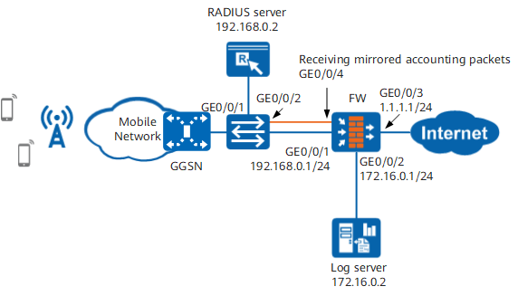
As shown in Figure 1, the FW is deployed at the Internet egress of the wireless network, connecting the intranet with the Internet. The session log recorded by the FW when a mobile phone user accesses the Internet must contain the mobile phone number. The FW sends logs to the eLog log server so that the administrator can view and analyze sessions on the eLog.
Configuration Roadmap

This example describes content related only to session log outputting.
The system time must be set correctly during the initial configuration. Changing the system time during device running will result in incorrect timestamps in historical logs. The time zone of the log server must be the same as that of the FW.
In a hot standby scenario, RADIUS accounting packets shall be mirrored to both the active and standby devices.
When a user accesses the Internet with a mobile phone, the user must be authenticated by the RADIUS server. The FW obtains and parses the accounting packet between the gateway device (GGSN) and RADIUS server to obtain the mapping between the user IP address and mobile phone number. In this way, the FW uses the mobile phone number as the value of the user name field in the session log and sends the session log to the log server.
- Enable the session log function in a security policy.
- Configure RADIUS SSO and enable user source tracing so that the FW can parse the RADIUS accounting packet and record the mapping between the IP address and mobile phone number.
- Configure log hosts.
- Configure the log output format and the source IP address and source port.
- In this example, the accounting packets exchanged between the gateway device and the RADIUS server do not pass the FW. You must configure the port mirroring function on the switch to mirror the RADIUS accounting packets to the FW.
Data Planning
Item |
Data |
Description |
|---|---|---|
RADIUS SSO |
|
Set SSO parameters on the FW for the FW to analyze the RADIUS accounting packets passing by to obtain mobile phone number and IP address mappings. |
Port mirroring on the switch |
|
- |
Procedure
- Configure the interfaces.
# Configure an IP address for GigabitEthernet 0/0/1.
<FW> system-view
[FW] interface GigabitEthernet 0/0/1
[FW-GigabitEthernet 0/0/1] ip address 192.168.0.1 24
[FW-GigabitEthernet 0/0/1] quit
# Configure an IP address for GigabitEthernet 0/0/2.
[FW] interface GigabitEthernet 0/0/2
[FW-GigabitEthernet 0/0/2] ip address 172.16.0.1 24
[FW-GigabitEthernet 0/0/2] quit
# Configure an IP address for GigabitEthernet 0/0/3.
[FW] interface GigabitEthernet 0/0/3
[FW-GigabitEthernet 0/0/3] ip address 1.1.1.1 24
[FW-GigabitEthernet 0/0/3] quit
# Configure GigabitEthernet 0/0/4 to work in switching mode.
[FW] interface GigabitEthernet 0/0/4
[FW-GigabitEthernet 0/0/4] portswitch
[FW-GigabitEthernet 0/0/4] port link-type trunk
[FW-GigabitEthernet 0/0/4] port trunk allow-pass vlan all
[FW-GigabitEthernet 0/0/4] quit
The interface that receives mirroring packets from the switch must work in switching mode. If the VLAN tag of the traffic is specified, in addition to running the port trunk allow-pass vlan vlan-id command to configure the allowed VLAN, you need also to create the corresponding VLAN on the FW.
# Add GigabitEthernet 0/0/1 and GigabitEthernet 0/0/4 to the trust zone.
[FW] firewall zone trust
[FW-zone-trust] add interface GigabitEthernet 0/0/1
[FW-zone-trust] add interface GigabitEthernet 0/0/4
[FW-zone-trust] quit
# Add GigabitEthernet 0/0/2 to the dmz zone.
[FW] firewall zone dmz
[FW-zone-dmz] add interface GigabitEthernet 0/0/2
[FW-zone-dmz] quit
# Add GigabitEthernet 0/0/3 to the untrust zone.
[FW] firewall zone untrust
[FW-zone-untrust] add interface GigabitEthernet 0/0/3
[FW-zone-untrust] quit
- Configure security policies.
# Configure a trust-untrust interzone security policy and enable the session log function. The session log function takes effect only when the policy action is set to permit.
[FW] security-policy
[FW-policy-security] rule name trust_untrust
[FW-policy-security-rule-trust_untrust] source-zone trust
[FW-policy-security-rule-trust_untrust] destination-zone untrust
[FW-policy-security-rule-trust_untrust] source-address 192.168.0.0 24
[FW-policy-security-rule-trust_untrust] action permit
[FW-policy-security-rule-trust_untrust] session logging
[FW-policy-security-rule-trust_untrust] quit
Session log packets are not subject to security policy. Therefore, you not do need to configure a security policy for session logs. Instead, you need to configure only the preceding security policies.
- Configure RADIUS SSO and enable user tracing.
[FW] user-manage single-sign-on radius
[FW-sso-radius] mode optical-splitter
[FW-sso-radius] interface GigabitEthernet 0/0/4
[FW-sso-radius] traffic server-ip 192.168.0.2 port 1813
[FW-sso-radius] enable
[FW-sso-radius] user-trace enable
[FW-sso-radius] quit
- Configure the log host.
- When the log format is syslog:
[FW] firewall log host 1 172.16.0.2 514
[FW] firewall log session log-type syslog
- If the log format is binary:
[FW] firewall log host 1 172.16.0.2 9002
[FW] firewall log session log-type binary
- When the log format is syslog:
- Configure the source IP address and source port.
[FW] firewall log source 172.16.0.1 6000 - Configure the port mirroring on the switch.
This example uses Huawei S9700 to describe how to configure the port mirroring function. For the configurations of other functions, refer to the product documents of the S9700.
# Configure GigabitEthernet 0/0/2 as the observing port.
<Switch> system-view
[Switch] observe-port 1 interface GigabitEthernet 0/0/2
# Configure GigabitEthernet 0/0/1 as the mirroring port to mirror outgoing traffic.
[Switch] interface GigabitEthernet 0/0/1
[Switch-GigabitEthernet 0/0/1] port-mirroring to observe-port 1 outbound
[Switch-GigabitEthernet 0/0/1] quit
As RADIUS accounting packets are sent from the gateway to the RADIUS server, you need to mirror the outgoing traffic of GigabitEthernet 0/0/1.
Configuration Verification
- Run the display user-manage user-trace table command on the FW to view the user source tracing entry.
<FW> display user-manage user-trace table Current Total Number: 3 -------------------------------------------------------- IP UserName Time-left -------------------------------------------------------- 10.1.1.1 139******** 23:59:58 10.1.1.2 139******** 23:59:57 10.1.1.3 138******** 23:59:56 - Choose on the eLog. The session log contains the mobile phone number.
Configuration Scripts
#
 sysname FW
#
user-manage single-sign-on radius
  enable
  user-trace enable
  interface GigabitEthernet 0/0/4
  traffic server-ip 192.168.0.2 port 1813
#
  firewall log host 1 172.16.0.2 9002
  firewall log source 172.16.0.1 6000
#
interface GigabitEthernet 0/0/4
 undo shutdown
 portswitch
 port link-type trunk
 port trunk allow-pass vlan all
#
interface GigabitEthernet 0/0/1
 undo shutdown
 ip address 192.168.0.1 255.255.255.0
#
interface GigabitEthernet 0/0/2
 undo shutdown
 ip address 172.16.0.1 255.255.255.0
#
interface GigabitEthernet 0/0/3
 undo shutdown
 ip address 1.1.1.1 255.255.255.0
#
firewall zone trust
 set priority 85
 add interface GigabitEthernet 0/0/1
 add interface GigabitEthernet 0/0/4
#
firewall zone untrust
 set priority 5
 add interface GigabitEthernet 0/0/3
#
firewall zone dmz
 set priority 50
 add interface GigabitEthernet 0/0/2
#
security-policy
 rule name trust_untrust
  session logging
  source-zone trust
  destination-zone untrust
  source-address 192.168.0.0 24
  action permit
#