Web Example: Configuring 5-Tuple Packet Capture
This section describes how to use the Web to configure 5-tuple packet capture, including setting the interface type and number, queue number, and IP address and port of the target host for receiving the captured packets.
Networking Requirements
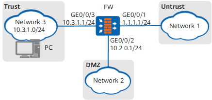
As shown in Figure 1, interfaces GigabitEthernet 0/0/1, GigabitEthernet 0/0/2, and GigabitEthernet 0/0/3 on the FW respectively connect to networks 1, 2, and 3. All the three interfaces have traffic. Log in to the FW from a PC to configure packet capture on interfaces GigabitEthernet 0/0/1 and download the captured packets to the PC.
Configuration Roadmap
Configure a packet capture queue for each interface on the FW, enable the packet capture process, and save the captured packets.
View the captured packets on the web UI.

Ensure that each interface has traffic before configuring packet capture. This example focuses on packet capture.
Procedure
- Set an IP address for each interface and assign the interfaces to security zones.
Choose .
In Interface List, click
 of GigabitEthernet 0/0/1 and set the parameters as follows:
Zone
untrust
IPv4
IP Address
1.1.1.1/24
Click OK.
- Configure security policies to allow packet transmission between a specified private network and the Internet.
Choose .
In Security Policy List, click Add, select Add Security Policy, and configure security policies based on the following parameter values.
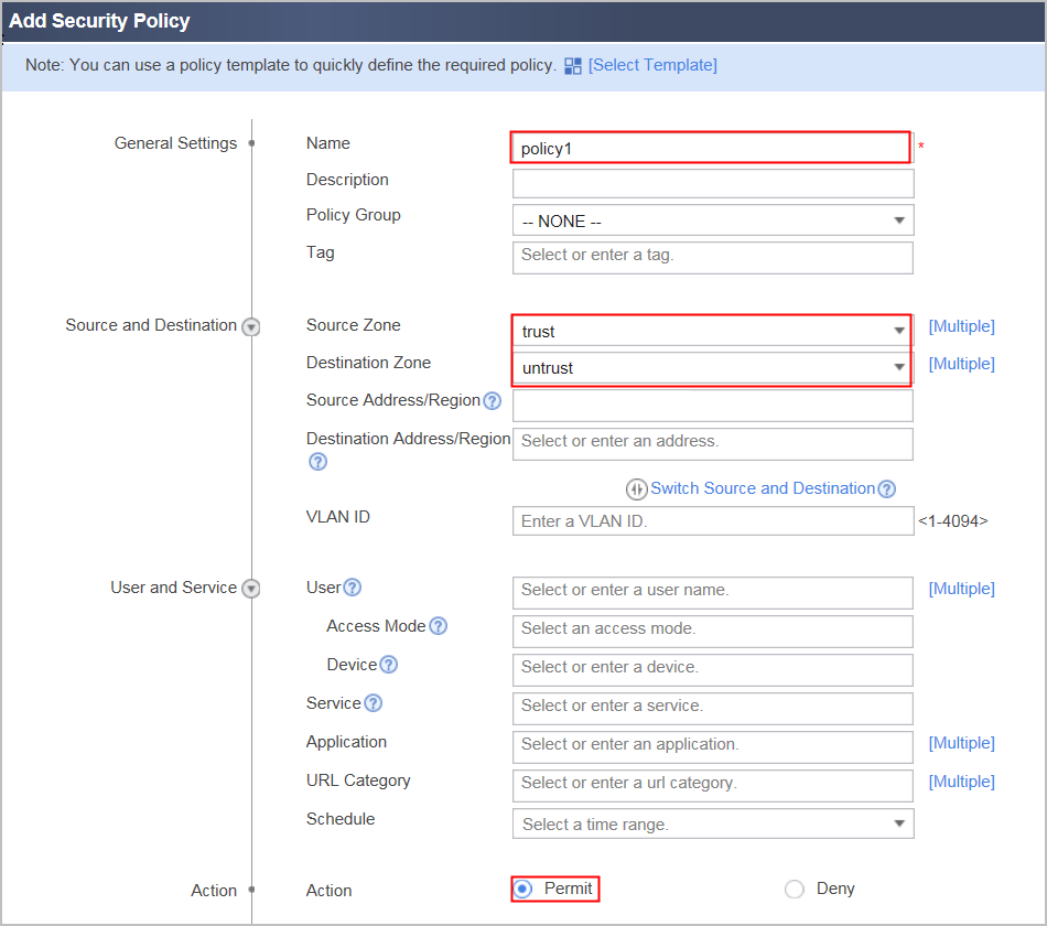
Name
policy1
Source Zone
trust
Destination Zone
untrust
Action
Permit
Name
policy2
Source Zone
untrust
Destination Zone
trust
Action
Permit
- Configure the packet capture queue.
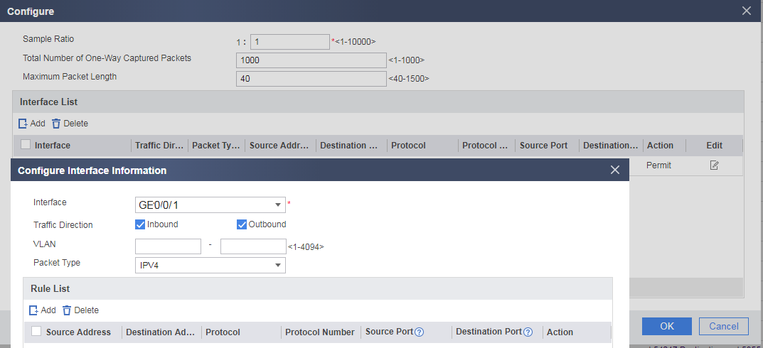
Choose and set the following parameter values.
- Click Start to capture packets.
The FW captures a maximum of 1000 packets at a time. If the FW captures inbound and outbound packets at the same time, a maximum of 2000 packets can be captured. Therefore, the FW can receive a maximum of 2000 packets. However, the 5-Tuple Packet Capture interface displays only 1000 packets.
You can view Received Packets and Percentage on the web UI to have an overview on received packets. Received Packets indicates the number of received packets, and Percentage indicates the percentage of received packets in the total capacity (1000 packets).

Ensure that you enable packet capture in off-peak hours to prevent misoperations from interrupting services.
- Click End to stop capturing packets.
- After locating network problems, click Clear to clear the captured packet queue.

