PIM-DM Mechanism
This section describes the related concepts and the multicast data forwarding process in a PIM-DM domain.
PIM-DM resolves P2MP data transmission problems on small-scale networks where users are densely distributed.
PIM-DM uses a flooding-pruning method to forward multicast data. PIM-DM is best applied to small-scale networks with a dense distribution of multicast group members. If a large number of Prune messages are generated on a large-scale network where multicast group members are sparsely distributed, it takes a long time to complete the flooding-pruning process.
PIM-DM constructs an MDT called SPT. PIM-DM assumes that all members are densely distributed on the network and that every network segment may have some members. Based on these assumptions, the multicast source first floods multicast data to each network segment and then prunes segments without any members. Through regular flooding and pruning, PIM-DM creates and maintains a unidirectional and loop-free SPT that connects the multicast source and group members.
Related Concepts
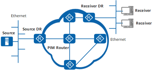
This section provides basic PIM-DM concepts, as shown in Figure 1.
PIM device
A multicast router that supports PIM is called a PIM device. A PIM-enabled interface on a PIM device is called a PIM interface.
Designated Router (DR)
There are two types of DRs on a PIM network:Multicast source's DR: A PIM device that is directly connected to the multicast source in a PIM-DM domain and is responsible for forwarding multicast data packets to other PIM devices.
Receiver's DR: A PIM device that is directly connected to group members (receiver hosts) and is responsible for forwarding multicast data to the group members.
Shortest path tree (SPT)
An SPT is a multicast distribution tree (MDT) with the multicast source as the root and group members as leaves. SPTs are used in PIM-DM, PIM-SM, and PIM-SSM.
Implementation
-
Each PIM device in a PIM-DM domain regularly sends Hello messages to other PIM devices in order to discover PIM neighbors and maintain PIM neighbor relationships.

By default, a PIM device permits other PIM control messages or multicast messages from a neighbor, irrespective of whether the PIM device has received Hello messages from the neighbor. However, if a PIM device has the neighbor check function, the PIM device permits other PIM control messages or multicast messages from a neighbor only after the PIM device has received Hello messages from the neighbor.
-
PIM-DM assumes that at least one multicast group member exists on each subnet, and floods multicast data to all routers on the network. Therefore, all PIM devices on the network can receive multicast data.
-
After flooding multicast data, PIM-DM prunes branches that have no multicast data receiver and keeps only the branches that have multicast data receivers. Only PIM devices that require multicast data can receive multicast data.
-
If a downstream device is in the prune state, the upstream device maintains a prune timer for this device. When the prune timer expires, the upstream device resumes forwarding data to the downstream device, which wastes network resources. To prevent this problem, the state-refresh capability can be enabled on the upstream router. The upstream router periodically sends State-Refresh messages to refresh the status of the prune timers maintained for all downstream devices. Downstream devices that do not require multicast data are kept constantly in the prune state.
-
If a node on a pruned branch has new group members, PIM-DM uses the graft mechanism to enable the node to immediately forward multicast data.
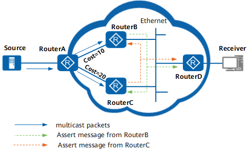
If there are multiple PIM devices on a network segment, the same multicast packets are sent repeatedly across the network segment. The Assert mechanism can be used to select a unique multicast data forwarder, preventing redundant multicast data forwarding.
Details of the PIM-DM implementation process are as follows:
Neighbor Discovery
The destination address is 224.0.0.13.
The source address is an interface address.
TTL is 1, indicating that packets are sent to neighbor interfaces only.
Hello messages are used to discover neighbors, adjust protocol parameters, and maintain neighbor relationships.
Discovering PIM neighbors
All PIM devices in the same network segment must receive multicast packets with the destination address of 224.0.0.13. Directly connected multicast routers receive Hello messages that contain neighbor information.
Adjusting protocol parameters
Hello messages are used to establish and maintain neighbor relationships. A Hello message carries the following protocol parameters:
DR_Priority: priority used by the router interface to elect the DR. The interface with the highest the priority is most likely to become the DR.
Holdtime: timeout period during which the neighbor is in the reachable state.
LAN_Delay: delay for transmitting Prune message on the shared network segment.
Neighbor-Tracking: neighbor tracking function.
Override-Interval: interval carried by a Hello messages for overriding a Prune message.
Maintaining neighbor relationship
PIM devices periodically exchange Hello messages. If a PIM device does not receive a new Hello messages from its PIM neighbor within the Holdtime, the router considers the neighbor unreachable and deletes the neighbor from its neighbor list.
Changes in PIM neighbor relationships lead to the changes in the multicast topology of the network. If an upstream or a downstream neighbor in the MDT is unreachable, multicast routes reconverge and the MDT is transferred.
Flooding
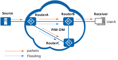
As shown in Figure 2, the source sends data to Router A and Router A then floods the data to all neighbors. Router B and Router C send data back and forth, but DM, using the Reverse Path Forwarding (RPF) mechanism, can ensure that data is received from only one direction. The RPF check is the basis for multicast routing. A device performs the RPF check on received packets to create or maintain multicast routing entries. The RPF check ensures that multicast data is forwarded along correct paths. When a device receives a multicast packet, the device searches the unicast routing table and static multicast routing table for an RPF route based on the source address contained in the packet. If the inbound interface of the packet matches the RPF interface, the packet passes the RPF check; otherwise, the packet fails. Finally, data is flooded to Router B that is connected to the receiver. Router B sends data to User A.
Prune
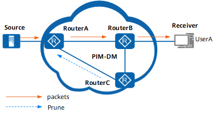
As shown in Figure 3, Router C has no receiver and needs no data, so it sends a Prune message upstream to Router A to instruct Router A to stop forwarding data to the interface connected to Router C.
Router A stops forwarding data to the downstream interface. This process is called pruning. Because Router A still has downstream interfaces in the forwarding state, Router A continues to forward multicast data to Router B. Router A, therefore, forwards subsequent packets to Router B. As a result, a unidirectional and loop-free SPT is set up from the source to User A.
State Refresh
As shown in Figure 3, if the network segment of the interface on Router C connected to Router A is in the prune state, Router A maintains a prune timer for Router C. When the prune timer expires, Router A resumes forwarding data to Router C. This results in a waste of network resources.
PIM-DM uses the state refresh feature to resolve this problem. The first hop nearest to the multicast source, namely, Router A, periodically floods the entire network with State-Refresh messages and resets the status of the prune timers on all multicast devices.
Graft
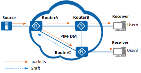
As shown in Figure 4, if Router C receives an IGMP Report message from User B (a host sends an IGMP Report message to a multicast router to join a multicast group or to respond to a Query message), Router C has a demand for data forwarding. To prevent an extended period of flooding-pruning, PIM-DM employs graft to implement fast data forwarding and enable new group members to rapidly receive multicast data.
Router C sends a Graft message upstream to require Router A to restore the forwarding status of the related downstream interface. Router A then restores the forwarding status of the downstream interface connected to Router C. Finally, multicast data is sent from this downstream interface to Router C.
Assert
As shown in Figure 5, Router B and Router C can receive multicast packets from the multicast source S and the multicast packets that pass the RPF check. (S, G) entries can be created on Router B and Router C. Because the downstream interfaces of Router B and Router C are connected to the same network segment, Router A and Router C can both send multicast data to the network segment. The Assert mechanism is used to ensure that only one multicast data forwarder exists in the network segment. The Assert process is as follows:
Router B receives a multicast packet from Router C through a downstream interface, but this packet fails the RPF check and is discarded by Router B. At the same time, Router B sends an Assert message to the network segment.
Router C compares its routing information with that carried in the Assert message sent by Router B. Router C fails because the route cost from Router B to the source is lower. The downstream interface of Router C is prohibited from forwarding multicast packets and deleted from the downstream interface list of the (S, G) entry.
Router C receives a multicast packet from Router B through the network segment, but the packet fails the RPF check and therefore is discarded.
The Assert process ends.