PIM-DM Control Message
PIM-DM devices implement multicast by exchanging PIM-DM control messages.
A PIM control message is encapsulated in an IP packet, as shown in Figure 1.

The value of the protocol type field in the IP header is 103. It indicates that the PIM message is encapsulated in the data field.
The destination address of the IP header identifies the receiver of the PIM message. The destination address can be either a unicast address or a multicast address.
PIM-DM and PIM-SM support different control messages.
Types of PIM Control Message
The headers of all PIM control messages use the same format, as shown in Figure 2.

Field |
Description |
|---|---|
Version |
Indicates the PIM version. The value is 2. |
Type |
Indicates the message type.
|
Reserved |
Indicates that this field is reserved. |
Checksum |
Indicates the checksum. |

The following part describes message types only related to PIM-DM.
Hello Message
PIM devices periodically send Hello messages through all PIM interfaces. PIM devices discover neighbors and maintain the neighbor relationship by exchanging Hello messages.
The source address of the IP packet encapsulated with the Hello message is the local interface address. The destination address is 224.0.0.13, and the TTL value is 1. The message is transmitted in multicast mode.
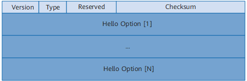

Field |
Description |
|---|---|
Type |
Indicates the message type. The value is 0. |
Reserved |
Indicates that this field is reserved. The field is set to 0 when the message is sent, and is ignored when the message is received. |
Checksum |
Indicates the checksum. |
OptionType |
Indicates the types of parameters. For the valid values, see Table 3. |
OptionLength |
Indicates the length of the Option Value field. |
OptionValue |
Indicates the values of parameters. |
OptionType |
OptionValue |
|---|---|
1 |
Holdtime: indicates the timeout period during which the neighbor is in the reachable state. If a router does not receive any Hello message in the timeout period, the router considers its neighbor unreachable. |
2 |
The field consists of the following parts:
|
19 |
DR Priority: indicates the priorities of the router interfaces that take part in the DR election. The higher the priority is, the more possible the interface wins in the election. |
20 |
Indicates the generation ID, a random number carried in the Hello message. It indicates the status of the neighbor. If the status of the neighbor changes, the random number is updated. When a router finds that the Hello messages received from the upstream contain different Generation ID values, the router considers that the upstream neighbor is lost or the status of the upstream neighbor changes. |
21 |
State Refresh Capable: indicates the interval for refreshing the status of the neighbor. |
24 |
Address List: indicates the secondary address list of PIM interfaces. |
Join/Prune Message
A Join/Prune message can contain both Join messages and Prune messages. The Join/Prune message that contains only a Join message is called Join message. The Join/Prune message that contains only a Prune message is called Prune message.
When the downstream interface of a PIM device does not have any receiving requirement, the PIM device sends a Prune message through the upstream interface to notify the upstream device of stopping forwarding packets to the network segment.
When a group member appears in the PIM-SM network, the DR at the group member side sends a Join message through Reverse Path Forwarding (RPF) interface towards the RP to notify the upstream neighbor of forwarding packets to the network segment. The Join message is sent to the upstream hop by hop. The RPT is set up.
When the RP triggers the SPT switchover, the RP sends a Join message through the RPF interface towards the source to notify the upstream neighbor of forwarding packets to the network segment. The Join message is sent to the upstream hop by hop. The RP-source tree is set up.
When the DR at the group member side triggers the SPT switchover, the DR sends a Join message through the RPF interface towards the source to notify the upstream neighbor of forwarding packets to network segment. The Join message is sent to the upstream hop by hop. The SPT is set up.
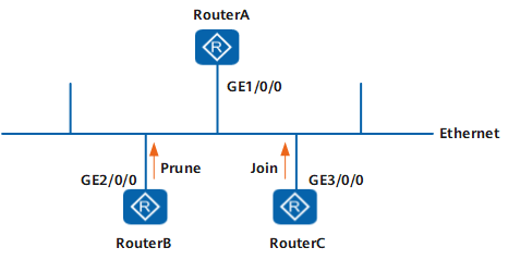
A PIM network segment may be connected to a downstream interface and multiple upstream interfaces. Assume that an upstream interface sends a Prune message. If other upstream interfaces still need to receive multicast packets, these interfaces must send the Join message within the override-interval. Otherwise, the downstream interfaces responsible for forwarding packets in the network segment cannot perform the prune action.
- On a multicast network, if PIM is enabled on the interfaces of the user-side routers, a member's DR is elected, and outbound interfaces are added to the PIM DR. The PIM DR sends Join messages to the RP.
- On a multicast network, if PIM is not enabled on the interfaces of the user-side routers, no members' DR is elected, and outbound interfaces are added to the IGMP querier. The IGMP sends Join messages to the RP.
As shown in Figure 5, GE1/0/0 of Router A is a downstream interface, and GE2/0/0 of RouterB and GE3/0/0 of RouterC are upstream interfaces. If RouterB sends a Prune message through GE2/0/0, GE3/0/0 of RouterC and GE1/0/0 of RouterA can receive the message. If RouterC still wants to receive the multicast data of the group, RouterC needs to send a Join message within the override-interval. GE1/0/0 of RouterA can know that a downstream router still wants to receive the multicast data. Therefore, RouterA does not perform the prune action.
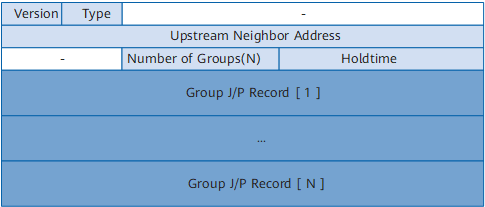
The source address of the IP packet encapsulated with Join/Prune message is the local interface address. The destination address is 224.0.0.13, and the TTL value is 1. The message is transmitted in multicast mode.
Field |
Description |
|---|---|
Type |
Indicates the message type. The value is 3. |
Upstream Neighbor Address |
Indicates the address of the upstream neighbor, that is, the address of the downstream interface that receives the Join/Prune message and performs the Join and Prune actions. |
Number of Groups |
Indicates the number of groups contained in the message. |
Holdtime |
Indicates the amount of time a receiver keeps the Join/Prune state, in seconds. |
Group Address |
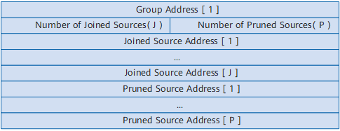
Indicates the group address. |
Number of Joined Sources |
Indicates the number of sources that the router joins. |
Number of Pruned Sources |
Indicates the number of sources that the router prunes. |
Joined Source Address |
Indicates the address of the source that the router joins. |
Pruned Source Address |
Indicates the address of the source that the router prunes. |
Assert Message
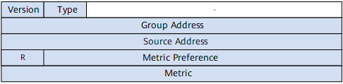
In the shared network segment, if a PIM device receives a (S, G) packet from the downstream interface of the (S, G) or (*, G) entry, it indicates that other forwarders exist in the network segment. The PIM device sends an Assert message through the downstream interface to take part in the election. The router that fails in the election stops forwarding multicast packets through the downstream interface.
The source address of the IP packet encapsulated with the Assert message is the local interface address, the destination address is 224.0.0.13, and the TTL value is 1. The packet is sent in multicast mode.
Field |
Description |
|---|---|
Type |
Indicates the message type. The value is 5. |
Group Address |
Indicates the group address. |
Source address |
If the router elects the unique forwarder of the (S, G) entry, the address is the source address. If the router elects the unique forwarder of the (*, G) entry, the address is 0. |
R |
Indicates the RPT bit. If the router elects the unique forwarder of the (S, G) entry, the bit is set to 0; if the router elects the unique forwarder of the (*, G) entry, the bit is set to 1. |
Metric Preference |
Indicates the priority of the unicast path to the source address. If the R field value is set 1, this field indicates the priority of the unicast path to the RP. |
Metric |
Indicates the cost of the unicast route to the source address. If the R field value is set 1, this field indicates the cost of the unicast path to the RP. |
Graft Message
In the PIM-DM network, when a router receives a Report message from a host, the router sends a Graft message through the upstream interface of the related (S, G) entry if the router is not on the SPT. The upstream neighbor immediately restores the forwarding of the downstream interface. If the upstream neighbor is not on the SPT, the neighbor continues to send the Graft message to the upstream.
The source address of the IP packet encapsulated with the Graft message is the local interface address and the destination address is the RPF neighbor. The packet is sent in unicast mode.
The format of the Graft message is the same as that of the Join/Prune message, as shown in Table 6. Only the values of partial fields are different.
Graft-Ack Message
In the PIM-DM network, when a router receives a Graft message from the downstream, the router restores the forwarding of the related downstream interface. At the same time, the router sends a Graft-Ack message through the downstream interface to notify that it has received the Graft message.
If the router that sends out the Graft message does not receive any Graft-Ack message in the set time, the router considers that the upstream does not receive the Graft message and resends it.
The source address of the IP packet encapsulated in the Graft-Ack message is the downstream interface address of an upstream device and the destination address is the address of the router that sends out the Graft message. The packet is sent in unicast mode.
The format of the Graft-Ack message is the same as that of the Graft message and copies some contents of the Graft message. Only the values of partial fields are different.
Field |
Description |
|---|---|
Type |
Indicates the message type. The value is 7. |
Upstream Neighbor Address |
Indicates the address of the router that sends out the Graft message. |
State-Refresh Message
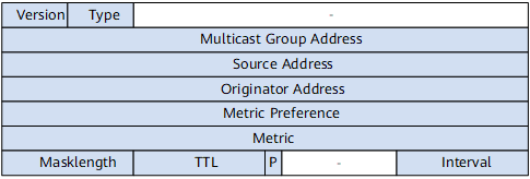
In the PIM-DM network, to avoid that the interface restores forwarding because the prune timer times out, the first-hop router nearest to the source periodically triggers State-Refresh messages. The State-Refresh message is flooded in the entire network and the statuses of prune timers on all routers are refreshed.
The source address of the IP packet encapsulated with the State-Refresh message is the downstream interface address, the destination address is 224.0.0.13, and the TTL value is 1. The packet is sent in multicast mode.
Field |
Description |
|---|---|
Type |
Indicates the message type. The value is 9. |
Multicast Group Address |
Indicates the group address. |
Source Address |
Indicates the source address. |
Originator Address |
Indicates the address of the first-hop router. |
Metric Preference |
Indicates the priority of the unicast route to the source. |
Metric |
Indicates the cost of the unicast route to the source. |
Masklength |
Indicates the address mask length of the unicast route to the source. |
TTL |
Indicates the TTL of the State-Refresh message. The TTL is used to limit the transmission range of the messages. The TTL value is reduced by 1 each time the State-Refresh message is forwarded by a router. |
P |
Indicates the prune indicator flag. If the State-Refresh message is sent out through the pruned interface, P is 1. Otherwise, P is 0. |
Interval |
Indicates the interval for sending State-Refresh messages. |