Example for Configuring a PIM-SM Network
In an autonomous system (AS) with reachable unicast routes, you can enable basic functions of PIM-SM so that user hosts can receive multicast data from any multicast source.
Networking Requirements
As shown in Figure 1, multicast is deployed in the Internet Service Provider (ISP) network. An integrated Interior Gateway Protocol (IGP) is deployed in the network. Unicast routes work normally and are connected to the Internet. It is required to perform proper configuration on FWs in the network to enable hosts to receive the Video On Demand (VOD) information in multicast mode.
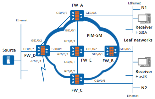
Device |
Interface |
IP address |
|---|---|---|
| FW_A | GE0/0/1 |
192.168.9.1/24 |
GE0/0/3 |
192.168.1.1/24 | |
GE0/0/5 |
10.110.1.1/24 | |
| FW_B | GE0/0/1 |
192.168.2.1/24 |
GE0/0/5 |
10.110.2.1/24 | |
| FW_C | GE0/0/2 |
192.168.3.1/24 |
GE0/0/6 |
10.110.2.2/24 | |
| FW_D | GE0/0/1 |
192.168.4.2/24 |
GE0/0/2 |
192.168.1.2/24 | |
GE0/0/4 |
10.110.4.1/24 | |
GE0/0/7 |
10.110.5.1/24 | |
| FW_E | GE0/0/1 |
192.168.3.2/24 |
GE0/0/2 |
192.168.2.2/24 | |
GE0/0/3 |
192.168.9.2/24 | |
GE0/0/4 |
192.168.4.1/24 |
Configuration Roadmap

The ISP network is accessed to the Internet. To expand services, PIM-SM is adopted to configure multicast functions, and Any-Source Multicast (ASM) and Source-Specific Multicast (SSM) models are used to provide multicast services.
Configure an IP address for each interface on FWs and a unicast routing protocol. PIM, an intra-domain multicast routing protocol, depends on unicast routing protocols. The multicast routing protocol can work normally only when unicast routing protocols work normally.
Enable the multicast function on all the FWs providing multicast services. PIM-SM can be configured only after multicast is enabled.
Enable PIM-SM on all interfaces of the multicast FWs. Other PIM-SM functions can be configured only after PIM-SM is enabled.
If IGMP needs to be configured on network-side interface, PIM-SM must be enabled before IGMP is enabled. The configuration order cannot be reversed; otherwise, the configuration of PIM-SM fails.
Enable IGMP on the interface connected to user hosts. A receiver can join and leave a multicast group freely by sending IGMP messages. Leaf FWs maintain the member relationship through IGMP.
Enable PIM silent on the FW interface connected to hosts to prevent malicious hosts from attacking the FW by simulating and sending PIM Hello packets; therefore, the security of multicast FWs can be ensured.
PIM silent is applicable only to the FW interface directly connected to the host network segment that is connected only to this FW.
Configure a Rendezvous Point (RP). The RP is a root node of a rendezvous point tree (RPT) tree in a PIM-SM network. It is recommended that you configure the RP on a FW through which many multicast flows pass, such as FW_E in the figure.
After creating an (*, G) entry according to the new multicast member relationship, the Designated router (DR) on the user side sends Join/Prune messages to the RP, updating the shared tree.
When a multicast data source starts to send data to groups, the DR unicasts a Register message to the RP. After receiving the Register message, the RP decapsulates it and then forwards it to other multicast members along the shared tree. At the same time, the RP sends a Register-Stop message to the DR on the multicast source side. After the Register-Stop message is received by the DR, the traffic can be switched from RPT to the shortest path tree (SPT).
(Optional) Configure the BootStrap router (BSR) boundary on the interface connected to the Internet. Bootstrap messages cannot pass through the BSR boundary; therefore, the BSR serves this PIM-SM domain only. In this manner, multicast services can be controlled effectively.
(Optional) Configure the SSM group address range on each FW. Ensure that multicast FWs in the PIM-SM domain provide services only for multicast groups in the SSM group address range. In this manner, multicast services can be controlled effectively.
Procedure
- Configure an IP address and a unicast routing protocol on each interface.
# Configure FW_A:
<FW_A> system-view
[FW_A] interface GigabitEthernet 0/0/1
[FW_A-GigabitEthernet0/0/1] ip address 192.168.9.1 24
[FW_A-GigabitEthernet0/0/1] quit
[FW_A] interface GigabitEthernet 0/0/3
[FW_A-GigabitEthernet0/0/3] ip address 192.168.1.1 24
[FW_A-GigabitEthernet0/0/3] quit
[FW_A] interface GigabitEthernet 0/0/5
[FW_A-GigabitEthernet0/0/5] ip address 10.110.1.1 24
[FW_A-GigabitEthernet0/0/5] quit
[FW_A] router id 1.1.1.1
[FW_A] ospf 1
[FW_A-ospf-1] area 0
[FW_A-ospf-1-area-0.0.0.0] network 192.168.9.0 0.0.0.255
[FW_A-ospf-1-area-0.0.0.0] network 192.168.1.0 0.0.0.255
[FW_A-ospf-1-area-0.0.0.0] network 10.110.1.0 0.0.0.255
[FW_A-ospf-1-area-0.0.0.0] quit
[FW_A-ospf-1] quit
# Configure FW_B:
<FW_B> system-view
[FW_B] interface GigabitEthernet 0/0/1
[FW_B-GigabitEthernet0/0/1] ip address 192.168.2.1 24
[FW_B-GigabitEthernet0/0/1] quit
[FW_B] interface GigabitEthernet 0/0/5
[FW_B-GigabitEthernet0/0/5] ip address 10.110.2.1 24
[FW_B-GigabitEthernet0/0/5] quit
[FW_B] router id 2.2.2.2
[FW_B] ospf 1
[FW_B-ospf-1] area 0
[FW_B-ospf-1-area-0.0.0.0] network 192.168.2.0 0.0.0.255
[FW_B-ospf-1-area-0.0.0.0] network 10.110.2.0 0.0.0.255
[FW_B-ospf-1-area-0.0.0.0] quit
[FW_B-ospf-1] quit
# Configure FW_C:
<FW_C> system-view
[FW_C] interface GigabitEthernet 0/0/2
[FW_C-GigabitEthernet0/0/2] ip address 192.168.3.1 24
[FW_C-GigabitEthernet0/0/2] quit
[FW_C] interface GigabitEthernet 0/0/6
[FW_C-GigabitEthernet0/0/6] ip address 10.110.2.2 24
[FW_C-GigabitEthernet0/0/6] quit
[FW_C] router id 3.3.3.3
[FW_C] ospf 1
[FW_C-ospf-1] area 0
[FW_C-ospf-1-area-0.0.0.0] network 192.168.3.0 0.0.0.255
[FW_C-ospf-1-area-0.0.0.0] network 10.110.2.0 0.0.0.255
[FW_C-ospf-1-area-0.0.0.0] quit
[FW_C-ospf-1] quit
# Configure FW_D:
<FW_D> system-view
[FW_D] interface GigabitEthernet 0/0/1
[FW_D-GigabitEthernet0/0/1] ip address 192.168.4.2 24
[FW_D-GigabitEthernet0/0/1] quit
[FW_D] interface GigabitEthernet 0/0/2
[FW_D-GigabitEthernet0/0/2] ip address 192.168.1.2 24
[FW_D-GigabitEthernet0/0/2] quit
[FW_D] interface GigabitEthernet 0/0/4
[FW_D-GigabitEthernet0/0/4] ip address 10.110.4.1 24
[FW_D-GigabitEthernet0/0/4] quit
[FW_D] interface GigabitEthernet 0/0/7
[FW_D-GigabitEthernet0/0/7] ip address 10.110.5.1 24
[FW_D-GigabitEthernet0/0/7] quit
[FW_D] router id 4.4.4.4
[FW_D] ospf 1
[FW_D-ospf-1] area 0
[FW_D-ospf-1-area-0.0.0.0] network 192.168.4.0 0.0.0.255
[FW_D-ospf-1-area-0.0.0.0] network 192.168.1.0 0.0.0.255
[FW_D-ospf-1-area-0.0.0.0] network 10.110.4.0 0.0.0.255
[FW_D-ospf-1-area-0.0.0.0] network 10.110.5.0 0.0.0.255
[FW_D-ospf-1-area-0.0.0.0] quit
[FW_D-ospf-1] quit
# Configure FW_E:
<FW_E> system-view
[FW_E] interface GigabitEthernet 0/0/1
[FW_E-GigabitEthernet0/0/1] ip address 192.168.3.2 24
[FW_E-GigabitEthernet0/0/1] quit
[FW_E] interface GigabitEthernet 0/0/2
[FW_E-GigabitEthernet0/0/2] ip address 192.168.2.2 24
[FW_E-GigabitEthernet0/0/2] quit
[FW_E] interface GigabitEthernet 0/0/3
[FW_E-GigabitEthernet0/0/3] ip address 192.168.9.2 24
[FW_E-GigabitEthernet0/0/3] quit
[FW_E] interface GigabitEthernet 0/0/4
[FW_E-GigabitEthernet0/0/4] ip address 192.168.4.1 24
[FW_E-GigabitEthernet0/0/4] quit
[FW_E] router id 5.5.5.5
[FW_E] ospf 1
[FW_E-ospf-1] area 0
[FW_E-ospf-1-area-0.0.0.0] network 192.168.3.0 0.0.0.255
[FW_E-ospf-1-area-0.0.0.0] network 192.168.2.0 0.0.0.255
[FW_E-ospf-1-area-0.0.0.0] network 192.168.9.0 0.0.0.255
[FW_E-ospf-1-area-0.0.0.0] network 192.168.4.0 0.0.0.255
[FW_E-ospf-1-area-0.0.0.0] quit
[FW_E-ospf-1] quit
- Enable multicast on all FWs and PIM-SM on all interfaces.
Enable multicast on all FWs and PIM-SM on all interfaces. The configurations of FW_B, FW_C, FW_D, and FW_E are the same as the configuration of FW_A, and are not mentioned here.
[FW_A] multicast routing-enable[FW_A] interface GigabitEthernet 0/0/5
[FW_A-GigabitEthernet0/0/5] pim sm
[FW_A-GigabitEthernet0/0/5] quit
[FW_A] interface GigabitEthernet 0/0/1
[FW_A-GigabitEthernet0/0/1] pim sm
[FW_A-GigabitEthernet0/0/1] quit
[FW_A] GigabitEthernet 0/0/3
[FW_A-GigabitEthernet0/0/3] pim sm
[FW_A-GigabitEthernet0/0/3] quit
- Enable IGMP on the interface connected to hosts.
On FW_A, enable IGMP on the interface connected to hosts. The configurations of FW_B and FW_C are the same as the configuration of FW_A, and are not mentioned here.
[FW_A] interface GigabitEthernet 0/0/5
[FW_A-GigabitEthernet0/0/5] igmp enable
[FW_A-GigabitEthernet0/0/5] igmp version 3
- Enable PIM silent on an interface of FW_A.
[FW_A] interface GigabitEthernet 0/0/5
[FW_A-GigabitEthernet0/0/5] pim silent
- Configure an RP.
RPs are classified into two types, that is, the static RP and the dynamic RP. You can configure the static RP and the dynamic at the same time or just configure one of them.
When the static RP and the dynamic RP are configured simultaneously, you can adjust parameters to specify the preferred RP.
This example shows how to configure the static RP and the dynamic RP, to prefer the dynamic RP, and specify the static RP as the standby RP by configuring the parameters.
# Configure the dynamic RP on one or more FWs in the PIM-SM domain. Set the service range of the RP advertisement and configure the Candidate-BSR (C-BSR) and the Candidate-RP (C-RP) on FW_E.
[FW_E] acl number 2005[FW_E-acl-basic-2005] rule permit source 225.1.1.0 0.0.0.255[FW_E-acl-basic-2005] quit[FW_E] pim[FW_E-pim] c-bsr GigabitEthernet 0/0/3
[FW_E-pim] c-rp GigabitEthernet 0/0/3 group-policy 2005 priority 0
# Configure the static RP on all multicast FWs. Configure FW_A, FW_B, FW_C, FW_D, and FW_E. The configurations on FW_B, FW_C, FW_D, and FW_E are similar to those on FW_A. The detailed configurations are not mentioned here.
If preferred is set in the static-rp x.x.x.x command, the static RP is preferred as the RP in the PIM-SM domain.
[FW_A] pim[FW_A-pim] static-rp 192.168.2.2 - On FW_D, configure the BSR boundary on the interface connected to the Internet.
[FW_D] interface GigabitEthernet 0/0/4
[FW_D-GigabitEthernet0/0/4] pim bsr-boundary
[FW_D-GigabitEthernet0/0/4] quit
- Configure the SSM group address range.
Set the SSM group address range to 232.1.1.0/24 on all FWs. The configurations of FW_B, FW_C, FW_D, and FW_E are the same as the configuration of FW_A, and are not mentioned here.
[FW_A] acl number 2000[FW_A-acl-basic-2000] rule permit source 232.1.1.0 0.0.0.255[FW_A-acl-basic-2000] quit[FW_A] pim[FW_A-pim] ssm-policy 2000 - Verify the configuration.
# Run the display pim interface command to view the configuration and running of PIM on an interface. The display of PIM on FW_C is as follows:
<FW_C> display pim interfaceVPN-Instance: public net
Interface State NbrCnt HelloInt DR-Pri DR-Address
GE0/0/6 up 0 30 1 10.110.2.2GE0/0/2 up 1 30 1 192.168.3.1# Run the display pim bsr-info command to view the BSR election on a FW. For example, the BSR information on FW_A and FW_E (including the C-BSR information on FW_E) is as follows:
<FW_A> display pim bsr-infoVPN-Instance: public net
Elected AdminScoped BSR Count: 0
Elected BSR Address: 192.168.9.2
Priority: 0
Hash mask length: 30
State: Accept Preferred
Scope: Not scoped
Uptime: 01:40:40
Expires: 00:01:42
C-RP Count: 1
<FW_E> display pim bsr-infoVPN-Instance: public net
Elected AdminScoped BSR Count: 0
Elected BSR Address: 192.168.9.2
Priority: 0
Hash mask length: 30
State: Elected
Scope: Not scoped
Uptime: 00:00:18
Next BSR message scheduled at :00:01:42
C-RP Count: 1
Candidate AdminScoped BSR Count: 0
Candidate BSR Address is: 192.168.9.2
Priority: 0
Hash mask length: 30
State:Elected
Scope: Not scoped
Wait to be BSR: 0
# Run the display pim rp-info command to view the RP information obtained by a FW. For example, the RP information on FW_A is as follows:
<FW_A> display pim rp-infoVPN-Instance: public net
PIM-SM BSR RP information:
Group/MaskLen: 225.1.1.0/24
RP: 192.168.9.2
Priority: 0
Uptime: 00:45:13
Expires: 00:02:17
PIM SM static RP information:
Static RP: 192.168.2.2
# Run the display pim routing-table command to view the PIM multicast routing table. Host A needs to receive the information about group 225.1.1.1/24, and Host B needs to receive the information sent by source 10.110.5.100/24 to group 232.1.1.1/24. The display is as follows:
<FW_A> display pim routing-tableVPN-Instance: public net
Total 1 (*, G) entry; 1 (S, G) entry
(*, 225.1.1.1)
RP: 192.168.9.2
Protocol: pim-sm, Flag: WC
UpTime: 00:13:46
Upstream interface: GigabitEthernet0/0/1Upstream neighbor: 192.168.9.2
RPF neighbor: 192.168.9.2
Downstream interface(s) information:
Total number of downstreams: 1
1: GigabitEthernet0/0/5,Protocol: igmp, UpTime: 00:13:46, Expires:-
(10.110.5.100, 225.1.1.1)
RP: 192.168.9.2
Protocol: pim-sm, Flag: SPT ACT
UpTime: 00:00:42
Upstream interface: GigabitEthernet0/0/3Upstream neighbor: 192.168.1.2
RPF neighbor: 192.168.1.2
Downstream interface(s) information:
Total number of downstreams: 1
1: GigabitEthernet0/0/5Protocol: pim-sm, UpTime: 00:00:42, Expires:-
<FW_D> display pim routing-tableVPN-Instance: public net
Total 0 (*, G) entry; 2 (S, G) entries
(10.110.5.100, 225.1.1.1)
RP: 192.168.9.2
Protocol: pim-sm, Flag: SPT ACT
UpTime: 00:00:42
Upstream interface: GigabitEthernet0/0/7Upstream neighbor: 10.110.5.100
RPF neighbor: 10.110.5.100
Downstream interface(s) information:
Total number of downstreams: 1
1: GigabitEthernet0/0/2Protocol: pim-sm, UpTime: 00:00:42, Expires:-
(10.110.5.100, 232.1.1.1)
Protocol: pim-ssm, Flag:
UpTime: 00:01:20
Upstream interface: GigabitEthernet0/0/7Upstream neighbor: 10.110.5.100
RPF neighbor: 10.110.5.100
Downstream interface(s) information:
Total number of downstreams: 1
1: GigabitEthernet0/0/1Protocol: pim-ssm, UpTime: 00:01:20, Expires:-
<FW_E> display pim routing-tableVPN-Instance: public net
Total 1 (*, G) entry; 1 (S, G) entry
(*, 225.1.1.1)
RP: 192.168.9.2 (local)
Protocol: pim-sm, Flag: WC
UpTime: 00:13:16
Upstream interface: Register
Upstream neighbor: 192.168.4.2
RPF neighbor: 192.168.4.2
Downstream interface(s) information:
Total number of downstreams: 1
1: GigabitEthernet0/0/3Protocol: pim-sm, UpTime: 00:13:16, Expires: 00:03:22
(10.110.5.100, 232.1.1.1)
Protocol: pim-ssm, Flag:
UpTime: 00:01:22
Upstream interface: GigabitEthernet0/0/4Upstream neighbor: 192.168.4.2
RPF neighbor: 192.168.4.2
Downstream interface(s) information:
Total number of downstreams: 1
1: GigabitEthernet0/0/1Protocol: pim-ssm, UpTime: 00:01:22, Expires:-
<FW_C> display pim routing-tableVPN-Instance: public net
Total 1 (S, G) entry
(10.110.5.100, 232.1.1.1)
Protocol: pim-ssm, Flag:
UpTime: 00:01:25
Upstream interface: GigabitEthernet0/0/2Upstream neighbor: 192.168.3.2
RPF neighbor: 192.168.3.2
Downstream interface(s) information:
Total number of downstreams: 1
1: GigabitEthernet0/0/6Protocol: igmp, UpTime: 00:01:25, Expires:-
Configuration Scripts
Configuration script of FW_A
#
sysname FW_A#
multicast routing-enable
#
acl number 2000
rule 5 permit source 232.1.1.0 0.0.0.255
#
interface GigabitEthernet0/0/5ip address 10.110.1.1 255.255.255.0
pim sm
igmp enable
igmp version 3
pim silent
#
interface GigabitEthernet0/0/3ip address 192.168.1.1 255.255.255.0
pim sm
#
interface GigabitEthernet0/0/1ip address 192.168.9.1 255.255.255.0
pim sm
#
ospf 1
area 0.0.0.0
network 10.110.1.0 0.0.0.255
network 192.168.1.0 0.0.0.255
network 192.168.9.0 0.0.0.255
#
pim
static-rp 192.168.2.2
ssm-policy 2000
#
return
Configuration script of FW_B
#
sysname FW_B#
multicast routing-enable
#
acl number 2000
rule 5 permit source 232.1.1.0 0.0.0.255
#
interface GigabitEthernet0/0/5ip address 10.110.2.1 255.255.255.0
pim sm
igmp enable
igmp version 3
pim silent
#
interface GigabitEthernet0/0/1ip address 192.168.2.1 255.255.255.0
pim sm
#
ospf 1
area 0.0.0.0
network 10.110.2.0 0.0.0.255
network 192.168.2.0 0.0.0.255
#
Pim
static-rp 192.168.2.2
ssm-policy 2000
#
return
Configuration script of FW_C
#
sysname FW_C#
multicast routing-enable
#
acl number 2000
rule 5 permit source 232.1.1.0 0.0.0.255
#
interface GigabitEthernet0/0/6ip address 10.110.2.2 255.255.255.0
pim sm
igmp enable
igmp version 3
pim silent
#
interface GigabitEthernet0/0/2ip address 192.168.3.1 255.255.255.0
pim sm
#
ospf 1
area 0.0.0.0
network 10.110.2.0 0.0.0.255
network 192.168.3.0 0.0.0.255
#
pim
static-rp 192.168.2.2
ssm-policy 2000
#
return
Configuration script of FW_D
#
sysname FW_D#
multicast routing-enable
#
acl number 2000
rule 5 permit source 232.1.1.0 0.0.0.255
#
interface GigabitEthernet0/0/7ip address 10.110.5.1 255.255.255.0
pim sm
igmp enable
igmp version 3
pim silent
#
interface GigabitEthernet0/0/4ip address 10.110.4.1 255.255.255.0
pim sm
pim bsr-boundary
#
interface GigabitEthernet0/0/2ip address 192.168.1.2 255.255.255.0
pim sm
#
interface GigabitEthernet0/0/1ip address 192.168.4.2 255.255.255.0
pim sm
#
ospf 1
area 0.0.0.0
network 10.110.4.0 0.0.0.255
network 10.110.5.0 0.0.0.255
network 192.168.1.0 0.0.0.255
network 192.168.4.0 0.0.0.255
#
pim
static-rp 192.168.2.2
ssm-policy 2000
#
return
Configuration script of FW_E
#
sysname FW_E#
multicast routing-enable
#
acl number 2000
rule 5 permit source 232.1.1.0 0.0.0.255
#
acl number 2005
rule 5 permit source 225.1.1.0 0.0.0.255
#
interface GigabitEthernet0/0/1ip address 192.168.3.2 255.255.255.0
pim sm
#
interface GigabitEthernet0/0/2ip address 192.168.2.2 255.255.255.0
pim sm
#
interface GigabitEthernet0/0/3ip address 192.168.9.2 255.255.255.0
pim sm
#
interface GigabitEthernet0/0/4ip address 192.168.4.1 255.255.255.0
pim sm
#
ospf 1
area 0.0.0.0
network 192.168.3.0 0.0.0.255
network 192.168.2.0 0.0.0.255
network 192.168.9.0 0.0.0.255
network 192.168.4.0 0.0.0.255
#
pim
c-bsr GigabitEthernet0/0/3c-rp GigabitEthernet0/0/3 group-policy 2005 priority 0static-rp 192.168.2.2
ssm-policy 2000
#
return