Example for Configuring the SPT Switchover in a PIM-SM Domain
By default, the Rendezvous Point (RP) and the DR at the group member side immediately perform the shortest path tree (SPT) switchover after they receive the first multicast data packet. If a receiver wants to perform the SPT switchover only when the rate of multicast data packets reaches the threshold, you need to configure triggering conditions for the SPT switchover.
Networking Requirements
Receivers can receive the Video On Demand (VOD) information in multicast mode. The SM-single BootStrap router (BSR) administrative domain is adopted in the entire PIM network. By default, the DR at the receiver side and the RP perform the SPT switchover immediately after receiving the first multicast data packet, and choose the optimal path to receive information from the source. If a receiver wants to perform the SPT switchover after the traffic reaches the threshold, you need to configure the SPT switchover.
As shown in Figure 1, it is required to perform proper configuration on FWs. Host A on the leaf network can receive multicast data from the RP (GE0/0/1 of FW_A). When the rate for forwarding multicast data reaches 1024 kbit/s, the SPT switchover is performed (After SPT switchover, the path used by Host A to receive multicast data is Source-FW_B-FW_C-Host A).
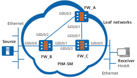
Device |
Interface |
IP address |
|---|---|---|
| FW_A | GE0/0/1 |
192.168.1.1/24 |
GE0/0/2 |
192.168.3.1/24 |
|
| FW_B | GE0/0/1 |
192.168.2.1/24 |
GE0/0/2 |
192.168.3.2/24 |
|
GE0/0/6 |
10.110.5.1/24 |
|
| FW_C | GE0/0/1 |
192.168.1.2/24 |
GE0/0/3 |
192.168.2.2/24 |
|
GE0/0/5 |
10.110.2.1/24 |
Configuration Roadmap
The configuration roadmap is as follows:
Configure an IP address and a unicast routing protocol for each interface.
Enable multicast on each FW, PIM-SM on each interface, and IGMP on the interface at the host side.
Configure GE0/0/1 of FW_A as the C-BSR and C-RP.
Perform the SPT switchover on FW_C.
Procedure
- Configure an IP address and a unicast routing protocol on each interface.
# Based on Figure 1, configure an IP address and mask of each interface, interconnect FWs through OSPF, ensure that FW_A, FW_B, and FW_C can interconnect at the network layer, and configure the three FWs to dynamically update routes through a unicast routing protocol.
# Configure FW_A:
<FW_A> system-view
[FW_A] interface GigabitEthernet 0/0/1
[FW_A-GigabitEthernet0/0/1] ip address 192.168.1.1 24
[FW_A-GigabitEthernet0/0/1] quit
[FW_A] interface GigabitEthernet 0/0/2
[FW_A-GigabitEthernet0/0/2] ip address 192.168.3.1 24
[FW_A-GigabitEthernet0/0/2] quit
[FW_A] router id 1.1.1.1
[FW_A] ospf 1
[FW_A-ospf-1] area 0
[FW_A-ospf-1-area-0.0.0.0] network 192.168.1.0 0.0.0.255
[FW_A-ospf-1-area-0.0.0.0] network 192.168.3.0 0.0.0.255
[FW_A-ospf-1-area-0.0.0.0] quit
[FW_A-ospf-1] quit
# Configure FW_B:
<FW_B> system-view
[FW_B] interface GigabitEthernet 0/0/1
[FW_B-GigabitEthernet0/0/1] ip address 192.168.2.1 24
[FW_B-GigabitEthernet0/0/1] quit
[FW_B] interface GigabitEthernet 0/0/2
[FW_B-GigabitEthernet0/0/2] ip address 192.168.3.2 24
[FW_B-GigabitEthernet0/0/2] quit
[FW_B] interface GigabitEthernet 0/0/6
[FW_B-GigabitEthernet0/0/6] ip address 10.110.5.1 24
[FW_B-GigabitEthernet0/0/6] quit
[FW_B] router id 2.2.2.2
[FW_B] ospf 1
[FW_B-ospf-1] area 0
[FW_B-ospf-1-area-0.0.0.0] network 192.168.2.0 0.0.0.255
[FW_B-ospf-1-area-0.0.0.0] network 192.168.3.0 0.0.0.255
[FW_B-ospf-1-area-0.0.0.0] network 10.110.5.0 0.0.0.255
[FW_B-ospf-1-area-0.0.0.0] quit
[FW_B-ospf-1] quit
# Configure FW_C
<FW_C> system-view
[FW_C] interface GigabitEthernet 0/0/1
[FW_C-GigabitEthernet0/0/1] ip address 192.168.1.2 24
[FW_C-GigabitEthernet0/0/1] quit
[FW_C] interface GigabitEthernet 0/0/3
[FW_C-GigabitEthernet0/0/3] ip address 192.168.2.2 24
[FW_C-GigabitEthernet0/0/3] quit
[FW_B] interface GigabitEthernet 0/0/5
[FW_B-GigabitEthernet0/0/5] ip address 10.110.2.1 24
[FW_B-GigabitEthernet0/0/5] quit
[FW_C] router id 3.3.3.3
[FW_C] ospf 1
[FW_C-ospf-1] area 0
[FW_C-ospf-1-area-0.0.0.0] network 192.168.1.0 0.0.0.255
[FW_C-ospf-1-area-0.0.0.0] network 192.168.2.0 0.0.0.255
[FW_C-ospf-1-area-0.0.0.0] network 10.110.2.0 0.0.0.255
[FW_C-ospf-1-area-0.0.0.0] quit
[FW_C-ospf-1] quit
- Enable multicast on each FW, PIM-SM on each interface, and IGMP on the interface at the host side.
# Enable multicast on each FW, PIM-SM on each interface, and IGMP on the interfaces that connect FW_C to the leaf network. The configurations of FW_A and FW_B are the same as the configuration of FW_C, and are not mentioned here.
[FW_C] multicast routing-enable[FW_C] interface GigabitEthernet 0/0/5
[FW_C-GigabitEthernet0/0/5] pim sm
[FW_C-GigabitEthernet0/0/5] igmp enable
[FW_C-GigabitEthernet0/0/5] igmp version 2
[FW_C-GigabitEthernet0/0/5] quit
[FW_C] interface GigabitEthernet 0/0/3
[FW_C-GigabitEthernet0/0/3] pim sm
[FW_C-GigabitEthernet0/0/3] quit
[FW_C] interface GigabitEthernet 0/0/1
[FW_C-GigabitEthernet0/0/1] pim sm
[FW_C-GigabitEthernet0/0/1] quit
- Configure a static RP.
# Configure the static RP on FW_A, FW_B, and FW_C. The configurations on FW_B and FW_C are similar to those on FW_A. The detailed configurations are not mentioned here.
[FW_A] pim[FW_A-pim] static-rp 192.168.1.1 - Configure the threshold of the SPT switchover.
# Perform the SPT switchover on FW_C when the rate of multicast data packets reaches 1024 kbit/s.
[FW_C] pim[FW_C-pim] spt-switch-threshold 1024[FW_C-pim] quit - Verify the configuration.
# The multicast source starts to send data to the group, and Host A can receive the data from the source. When the rate is smaller than 1024 kbit/s, run the display pim routing-table command to view the PIM multicast routing table. You can find that the upstream neighbor is FW_A. The display is as follows:
<FW_C> display pim routing-tableVPN-Instance: public net
Total 1 (*, G) entry; 1 (S, G) entry
(*, 225.1.1.1)
RP: 192.168.1.1
Protocol: pim-sm, Flag: WC
UpTime: 00:13:46
Upstream interface: GigabitEthernet0/0/1,Upstream neighbor: 192.168.1.1
RPF neighbor: 192.168.1.1
Downstream interface(s) information:
Total number of downstreams: 1
1: GigabitEthernet0/0/5,Protocol: igmp, UpTime: 00:13:46, Expires:-
(10.110.5.100, 225.1.1.1)
RP: 192.168.1.1
Protocol: pim-sm, Flag: ACT
UpTime: 00:00:42
Upstream interface: GigabitEthernet0/0/1Upstream neighbor: 192.168.1.1
RPF neighbor: 192.168.1.1
Downstream interface(s) information:
Total number of downstreams: 1
1: GigabitEthernet0/0/5Protocol: pim-sm, UpTime: 00:00:42, Expires:-
# When the rate is greater than 1024 kbit/s, run the display pim routing-table command to view the PIM multicast routing table on the FW. You can find that the upstream neighbor is FW_B. The display is as follows:
<FW_C> display pim routing-tableVPN-Instance: public net
Total 1 (*, G) entry; 1 (S, G) entry
(*, 225.1.1.1)
RP: 192.168.1.1
Protocol: pim-sm, Flag: WC
UpTime: 00:13:46
Upstream interface: GigabitEthernet0/0/2,Upstream neighbor: 192.168.2.2
RPF neighbor: 192.168.2.2
Downstream interface(s) information:
Total number of downstreams: 1
1: GigabitEthernet0/0/5,Protocol: igmp, UpTime: 00:13:46, Expires:-
(10.110.5.100, 225.1.1.1)
RP: 192.168.1.1
Protocol: pim-sm, Flag:RPT SPT ACT
UpTime: 00:00:42
Upstream interface: GigabitEthernet0/0/2Upstream neighbor: 192.168.2.2
RPF neighbor: 192.168.2.2
Downstream interface(s) information:
Total number of downstreams: 1
1: GigabitEthernet0/0/5Protocol: pim-sm, UpTime: 00:00:42, Expires:-
Configuration Scripts
Configuration script of FW_A
#
sysname FW_A#
multicast routing-enable
#
interface GigabitEthernet0/0/1ip address 192.168.1.1 255.255.255.0
pim sm
#
interface GigabitEthernet0/0/2ip address 192.168.3.1 255.255.255.0
pim sm
#
pim
static-rp 192.168.1.1
#
ospf 1
area 0.0.0.0
network 192.168.1.0 0.0.0.255
network 192.168.3.0 0.0.0.255
#
return
Configuration script of FW_B
#
sysname FW_B#
multicast routing-enable
#
interface GigabitEthernet0/0/6ip address 10.110.5.1 255.255.255.0
pim sm
#
interface GigabitEthernet0/0/1ip address 192.168.2.1 255.255.255.0
pim sm
#
interface GigabitEthernet0/0/2ip address 192.168.3.2 255.255.255.0
pim sm
#
pim
static-rp 192.168.1.1
#
ospf 1
area 0.0.0.0
network 10.110.5.0 0.0.0.255
network 192.168.2.0 0.0.0.255
network 192.168.3.0 0.0.0.255
#
return
Configuration script of FW_C
#
sysname FW_C#
multicast routing-enable
#
interface GigabitEthernet0/0/1ip address 192.168.1.2 255.255.255.0
pim sm
#
interface GigabitEthernet0/0/5ip address 10.110.2.1 255.255.255.0
pim sm
igmp enable
igmp version 2
#
interface GigabitEthernet0/0/3ip address 192.168.2.2 255.255.255.0
pim sm
#
pim
spt-switch-threshold 1024
static-rp 192.168.1.1
#
ospf 1
area 0.0.0.0
network 10.110.2.0 0.0.0.255
network 192.168.1.0 0.0.0.255
network 192.168.2.0 0.0.0.255
#
return