Inter-Domain Multicast in MSDP
This section describes the principle and implementation mechanism of inter-domain multicast between MSDP peers.
MSDP Peer Relationship
In MSDP, inter-domain multicast correctly addresses the problem that Rendezvous Point (RP) information and multicast source information are isolated between different PIM-SM domains. As a result, RPs can communicate with each other, multicast source information is shared, and multicast services can be forwarded between PIM-SM domains.
The MSDP peer relationship can be configured in the following ways:
Establish MSDP peer relationships between RPs in the same autonomous system (AS) but of different PIM-SM domains.
Establish MSDP peer relationships between RPs in different ASs.

To ensure successful Reverse Path Forwarding (RPF) checks in an inter-AS scenario, a BGP peer relationship must be established on the same interfaces as the MSDP peer relationship.
Basic Principle
Setting up the MSDP peer relationships between RPs in different PIM-SM domains ensures communications between MSDP peers (RPs). This procedure forms an MSDP-connected graph.
MSDP peers then exchange Source Active (SA) messages. The SA message carries (S, G) information registered on RP of the source DR. SA messages are exchanged among MSDP peers. This exchange ensures that SA messages sent by an RP can be received by all the other RPs.
As shown in Figure 1, the PIM-SM network is divided into four PIM-SM domains. The multicast source of PIM-SM1 domain (Source) sends data to the multicast group G. Receiver in the PIM-SM3 domain, as a member of G, maintains an RP-rooted Shared Tree (RPT) of G with RP3.
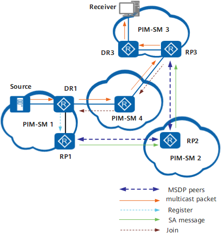
As shown in Figure 1, Receiver can receive the multicast data sent by Source after the MSDP peer relationships between RP1, RP2, and RP3 are set up.
Source sends multicast data to G. DR1 (Designated Router) then encapsulates the data into the Register message and sends the message to RP1. As the RP of the multicast source, RP1 creates an SA message, which carries the IP addresses of the multicast source, multicast group G, and RP1, and sends the SA message to the peer RP2.
After RP2 receives the SA message, it performs an RPF check on the message. If the check succeeds, RP2 forwards the message to RP3.
After RP3 receives the SA message, it performs an RPF check on the message, and the check succeeds. RP3 has the (*, G) entry, and the domain contains the member of G.
RP3 creates an (S, G) entry and sends a Join message with the (S, G) information to Source hop by hop. A multicast path (source tree) from Source to RP3 is set up. After the multicast data reaches RP3 along the source tree, RP3 forwards it to Receiver along the RPT.
After Receiver receives the multicast data, it determines whether to initiate the SPT switchover.