Example for Configuring Multicast Load Splitting
After a stable-preferred multicast load splitting policy is configured, multicast traffic can be distributed to multiple equal-cost routes for transmission.
Networking Requirements
Multicast route selection is based on the Reverse Path Forwarding (RPF) check, and the route selection policy depends on unicast routes. The selected unique route is used to guide the forwarding of multicast data. If the volume of multicast traffic is excessively large on a network, the network may be congested and multicast services may be affected. Multicast load splitting extends the rules of multicast route selection and makes multicast route selection not completely depend on the RPF check. When there are multiple equal-cost optimal routes on a network and the routes can be used to forward multicast data, multicast load splitting can be performed among the routes for multicast traffic.
Currently, multicast load splitting is classified into multicast source-based load splitting, multicast group-based load splitting, and multicast source- and multicast group-based load splitting. These types of multicast load splitting cannot meet the requirements of multicast splitting in all scenarios. In the case that multicast routing entries and network configurations are stable, RPF interfaces and RPF neighbors keep unchanged. When the number of entries is excessively small, balanced load splitting cannot be achieved.
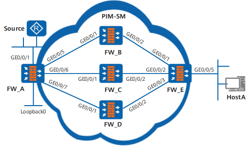
Stable-preferred load splitting consummates the preceding types of multicast load splitting. As shown in Figure 1, there are three equal-cost routes between FW_E connected to Host A and the multicast source, and stable-preferred load splitting is configured on FW_E. Therefore, entries can be evenly distributed on the equal-cost routes and balanced load splitting can be implemented among the equal-cost routes.
If the forwarding capabilities and the severities of traffic congestion of the three equal-cost routes on FW_E are different, balanced load splitting cannot meet network requirements. In this case, you need to configure unbalanced load splitting on FW_E, and set different load splitting weights on the upstream interfaces of FW_E to change the number of entries distributed to the equal-cost routes. Therefore, you can flexibly control the number of entries distributed on the equal-cost routes.
Device |
Interface |
IP address |
|---|---|---|
FW_A |
GE0/0/1 |
10.110.1.2/24 |
GE0/0/5 |
192.168.1.1/24 |
|
GE0/0/6 |
192.168.2.1/24 |
|
GE0/0/7 |
192.168.3.1/24 |
|
LoopBack0 |
1.1.1.1/32 |
|
| FW_B | GE0/0/1 |
192.168.1.2/24 |
GE0/0/2 |
192.168.4.1/24 |
|
| FW_C | GE0/0/1 |
192.168.2.2/24 |
GE0/0/2 |
192.168.5.1/24 |
|
| FW_D | GE0/0/1 |
192.168.3.2/24 |
GE0/0/2 |
192.168.6.1/24 |
|
| FW_E | GE0/0/1 |
192.168.4.2/24 |
GE0/0/2 |
192.168.5.2/24 |
|
GE0/0/3 |
192.168.6.2/24 |
|
GE0/0/5 |
10.110.2.2/24 |
Configuration Roadmap
The configuration roadmap is as follows:
Assign an IP address to each interface on FWs.
Configure IS-IS to implement interworking among FWs and ensure that route costs are equal.
Enable multicast on FW_s, enable PIM-SM on each interface, and set the loopback interface on FW_A as a Rendezvous Point (RP).
Configure stable-preferred multicast load splitting on FW_E to ensure the stability of multicast services.
Host A requires to receive data from some multicast groups for a long period. Therefore, configure the interfaces at the host side of FW_E to join the multicast groups statically in batches.
Host A requires to receive data from a new multicast group. Therefore, configure a multicast load splitting weight for each upstream interface on FW_E to achieve unbalanced multicast load splitting.
Procedure
- Assign an IP address to each interface on the FWs according to Figure 1.
Configure FW_A (the procedures for configuring FW_B and FW_C are the same as the procedure for configuring FW_A and therefore are not described).
# Assign an IP address to GigabitEthernet 0/0/1.
<FW> system-view
[FW] interface GigabitEthernet 0/0/1
[FW_A-GigabitEthernet0/0/1] ip address 10.110.1.2 24
[FW_A-GigabitEthernet0/0/1] quit
# Assign an IP address to GigabitEthernet 0/0/5.
[FW] interface GigabitEthernet 0/0/5
[FW_A-GigabitEthernet0/0/5] ip address 192.168.1.1 24
[FW_A-GigabitEthernet0/0/5] quit
# Assign an IP address to GigabitEthernet 0/0/6.
[FW] interface GigabitEthernet 0/0/6
[FW_A-GigabitEthernet0/0/6] ip address 192.168.2.1 24
[FW_A-GigabitEthernet0/0/6] quit
# Assign an IP address to GigabitEthernet 0/0/7.
[FW] interface GigabitEthernet 0/0/7
[FW_A-GigabitEthernet0/0/7] ip address 192.168.3.1 24
[FW_A-GigabitEthernet0/0/7] quit
# Assign an IP address to LoopBack0.
[FW_A] interface LoopBack0
[FW_A-LoopBack0] ip address 1.1.1.1 24
[FW_A-LoopBack0] quit
- Configure IS-IS to implement interworking among FWs and ensure that
route costs are equal.
# Configure FW_A.
[FW_A] isis 1
[FW_A-isis-1] network-entity 10.0000.0000.0001.00
[FW_A-isis-1] quit
[FW_A] interface GigabitEthernet0/0/1
[FW_A-GigabitEthernet0/0/1] isis enable 1
[FW_A-GigabitEthernet0/0/1] quit
[FW_A] interface GigabitEthernet0/0/5
[FW_A-GigabitEthernet0/0/5] isis enable 1
[FW_A-GigabitEthernet0/0/5] quit
[FW_A] interface GigabitEthernet0/0/6
[FW_A-GigabitEthernet0/0/6] isis enable 1
[FW_A-GigabitEthernet0/0/6] quit
[FW_A] interface GigabitEthernet0/0/7
[FW_A-GigabitEthernet0/0/7] isis enable 1
[FW_A-GigabitEthernet0/0/7] quit
# Configure FW_B.
[FW_A] isis 1
[FW_A-isis-1] network-entity 10.0000.0000.0002.00
[FW_A-isis-1] quit
[FW_A] interface GigabitEthernet0/0/1
[FW_A-GigabitEthernet0/0/1] isis enable 1
[FW_A-GigabitEthernet0/0/1] quit
[FW_A] interface GigabitEthernet0/0/2
[FW_A-GigabitEthernet0/0/2] isis enable 1
[FW_A-GigabitEthernet0/0/2] quit
# Configure FW_C.
[FW_C] isis 1
[FW_C-isis-1] network-entity 10.0000.0000.0003.00
[FW_C-isis-1] quit
[FW_C] interface GigabitEthernet0/0/1
[FW_C-GigabitEthernet0/0/1] isis enable 1
[FW_C-GigabitEthernet0/0/1] quit
[FW_C] interface GigabitEthernet0/0/2
[FW_C-GigabitEthernet0/0/2] isis enable 1
[FW_C-GigabitEthernet0/0/2] quit
# Configure FW_D.
[FW_D] isis 1
[FW_D-isis-1] network-entity 10.0000.0000.0004.00
[FW_D-isis-1] quit
[FW_D] interface GigabitEthernet0/0/1
[FW_D-GigabitEthernet0/0/1] isis enable 1
[FW_D-GigabitEthernet0/0/1] quit
[FW_D] interface GigabitEthernet0/0/2
[FW_D-GigabitEthernet0/0/2] isis enable 1
[FW_D-GigabitEthernet0/0/2] quit
# Configure FW_E.
[FW_E] isis 1
[FW_E-isis-1] network-entity 10.0000.0000.0005.00
[FW_E-isis-1] quit
[FW_E] interface GigabitEthernet0/0/1
[FW_E-GigabitEthernet0/0/1] isis enable 1
[FW_E-GigabitEthernet0/0/1] quit
[FW_E] interface GigabitEthernet0/0/2
[FW_E-GigabitEthernet0/0/2] isis enable 1
[FW_E-GigabitEthernet0/0/2] quit
[FW_E] interface GigabitEthernet0/0/3
[FW_E-GigabitEthernet0/0/3] isis enable 1
[FW_E-GigabitEthernet0/0/3] quit
[FW_E] interface GigabitEthernet0/0/5
[FW_E-GigabitEthernet0/0/5] isis enable 1
[FW_E-GigabitEthernet0/0/5] quit
- Enable multicast on all FWs and enable PIM-SM
on each interface.
Configure FW_A. Configurations on FWs B, C, D, and E are similar to those on FW_A. Therefore, configurations on these FWs are not mentioned here.
[FW_A] multicast routing-enable
[FW_A] interface GigabitEthernet 0/0/1
[FW_A-GigabitEthernet0/0/1] pim sm
[FW_A-GigabitEthernet0/0/1] quit
[FW_A] interface GigabitEthernet 0/0/5
[FW_A-GigabitEthernet0/0/5] pim sm
[FW_A-GigabitEthernet0/0/5] quit
[FW_A] interface GigabitEthernet 0/0/6
[FW_A-GigabitEthernet0/0/6] pim sm
[FW_A-GigabitEthernet0/0/6] quit
[FW_A] interface GigabitEthernet 0/0/7
[FW_A-GigabitEthernet0/0/7] pim sm
[FW_A-GigabitEthernet0/0/7] quit
[FW_A] interface loopback 0
[FW_A-LoopBack0] pim sm
[FW_A-LoopBack0] quit
- Configure an RP on FW_A.
Configure the interface loopback0 on FW_A as an RP.
[FW_A] pim
[FW_A-pim] c-bsr loopback 0
[FW_A-pim] c-rp loopback 0
[FW_A-pim] quit
- Configure stable-preferred multicast load splitting on FW_E.
[FW_E] multicast load-splitting stable-preferred - Configure the interfaces at the host side of FW_E to join the
multicast groups statically in batches.
Configure GE0/0/5 to join multicast groups from 225.1.1.1 to 225.1.1.3 statically.
[FW_E] interface GigabitEthernet 0/0/5
[FW_E-GigabitEthernet0/0/5] igmp static-group 225.1.1.1 inc-step-mask 32 number 3
[FW_E-GigabitEthernet0/0/5] quit
- Verify the configuration about stable-preferred multicast
load splitting.
The multicast source (10.110.1.1/24) sends multicast data to multicast groups (225.1.1.1 to 225.1.1.3). Host A can receive the multicast data from the source. On FW_E, check brief information about the PIM routing table.
<FW_E> display pim routing-table brief
 VPN-Instance: public net
 Total 9 (*, G) entry; 9 (S, G) entries

  00001.(*, 225.1.1.1)
       Upstream interface:GigabitEthernet0/0/3
       Number of downstream:1
       Number of receive vrf:0
  00002.(10.110.1.1, 225.1.1.1)
       Upstream interface:GigabitEthernet0/0/3
       Number of downstream:1
       Number of receive vrf:0
  00003.(*, 225.1.1.2)
       Upstream interface:GigabitEthernet0/0/2
       Number of downstream:1
       Number of receive vrf:0
  00004.(10.110.1.1, 225.1.1.2)
       Upstream interface:GigabitEthernet0/0/2
       Number of downstream:1
       Number of receive vrf:0
  00005.(*, 225.1.1.3)
       Upstream interface:GigabitEthernet0/0/1
       Number of downstream:1
       Number of receive vrf:0
  00006.(10.110.1.1, 225.1.1.3)
       Upstream interface:GigabitEthernet0/0/1
       Number of downstream:1
       Number of receive vrf:0
You can find that (*, G) and (S, G) entries are equally distributed to three equal-cost routes, with the upstream interfaces being GE0/0/3, GE0/0/2, and GE0/0/1 respectively.

The load splitting algorithm processes (*, G) and (S, G) entries separately and the process rules are the same.
- Configure multicast load splitting weights for different
upstream interfaces of FW_E to achieve unbalanced multicast load splitting.
# Set the multicast load splitting weight on GE0/0/1 to 2.
[FW_E] interface GigabitEthernet 0/0/1
[FW_E-GigabitEthernet0/0/1] multicast load-splitting weight 2
[FW_E-GigabitEthernet0/0/1] quit
# Set the multicast load splitting weight on GE0/0/3 to 0.
[FW_E] interface GigabitEthernet 0/0/3
[FW_E-GigabitEthernet0/0/3] multicast load-splitting weight 0
[FW_E-GigabitEthernet0/0/3] quit
- Configure the interfaces at the host side of FW_E to join new
multicast groups statically in batches.
# Configure GE0/0/5 to join multicast groups from 225.1.1.4 to 225.1.1.9 statically.
[FW_E] interface GigabitEthernet 0/0/5
[FW_E-GigabitEthernet0/0/5] igmp static-group 225.1.1.4 inc-step-mask 32 number 6
[FW_E-GigabitEthernet0/0/5] quit
- Verify the configuration about unbalanced multicast load
splitting.
# The multicast source (10.110.1.1/24) sends multicast data to multicast groups (225.1.1.1 to 225.1.1.9). Host A can receive the multicast data from the source. On FW_E, check brief information about the PIM routing table.
<FW_E> display pim routing-table brief
 VPN-Instance: public net
 Total 9 (*, G) entry; 9 (S, G) entries

  00001.(*, 225.1.1.1)
       Upstream interface:GigabitEthernet0/0/3
       Number of downstream:1
       Number of receive vrf:0
  00002.(10.110.1.1, 225.1.1.1)
       Upstream interface:GigabitEthernet0/0/3
       Number of downstream:1
       Number of receive vrf:0
  00003.(*, 225.1.1.2)
       Upstream interface:GigabitEthernet0/0/2
       Number of downstream:1
       Number of receive vrf:0
  00004.(10.110.1.1, 225.1.1.2)
       Upstream interface:GigabitEthernet0/0/2
       Number of downstream:1
       Number of receive vrf:0
  00005.(*, 225.1.1.3)
       Upstream interface:GigabitEthernet0/0/1
       Number of downstream:1
       Number of receive vrf:0
  00006.(10.110.1.1, 225.1.1.3)
       Upstream interface:GigabitEthernet0/0/1
       Number of downstream:1
       Number of receive vrf:0
  00007.(*, 225.1.1.4)
       Upstream interface:GigabitEthernet0/0/1
       Number of downstream:1
       Number of receive vrf:0
  00008.(10.110.1.1, 225.1.1.4)
       Upstream interface:GigabitEthernet0/0/1
       Number of downstream:1
       Number of receive vrf:0
  00009.(*, 225.1.1.5)
       Upstream interface:GigabitEthernet0/0/1
       Number of downstream:1
       Number of receive vrf:0
  00010.(10.110.1.1, 225.1.1.5)
       Upstream interface:GigabitEthernet0/0/1
       Number of downstream:1
       Number of receive vrf:0
  00011.(*, 225.1.1.6)
       Upstream interface:GigabitEthernet0/0/1
       Number of downstream:1
       Number of receive vrf:0
  00012.(10.110.1.1, 225.1.1.6)
       Upstream interface:GigabitEthernet0/0/1
       Number of downstream:1
       Number of receive vrf:0
  00013.(*, 225.1.1.7)
       Upstream interface:GigabitEthernet0/0/2
       Number of downstream:1
       Number of receive vrf:0
  00014.(10.110.1.1, 225.1.1.7)
       Upstream interface:GigabitEthernet0/0/1
       Number of downstream:1
       Number of receive vrf:0
  00015.(*, 225.1.1.8)
       Upstream interface:GigabitEthernet0/0/1
       Number of downstream:1
       Number of receive vrf:0
  00016.(10.110.1.1, 225.1.1.8)
       Upstream interface:GigabitEthernet0/0/2
       Number of downstream:1
       Number of receive vrf:0
  00017.(*, 225.1.1.9)
       Upstream interface:GigabitEthernet0/0/1
       Number of downstream:1
       Number of receive vrf:0
  00018.(10.110.1.1, 225.1.1.9)
       Upstream interface:GigabitEthernet0/0/1
       Number of downstream:1
       Number of receive vrf:0
The upstream interfaces of existent (*, G) and (S, G) entries keep unchanged. Since the multicast load splitting weight of GE0/0/1 is higher than that of GE0/0/2, the newly generated entries with the upstream interface being GE0/0/1 are more than those with the upstream interface being GE0/0/2. The multicast load splitting weight of GE0/0/3 is 0, which indicates that this interface does not take part in load splitting of new entries.
Configuration Scripts
Configuration script of FW_A
#
 sysname FW_A
#
 multicast routing-enable
#
isis 1
 network-entity 10.0000.0000.0001.00
#
interface GigabitEthernet0/0/1
 ip address 10.110.1.2 255.255.255.0
 isis enable 1
 pim sm
#
interface GigabitEthernet0/0/5
 ip address 192.168.1.1 255.255.255.0
 isis enable 1
 pim sm
#
interface GigabitEthernet0/0/6
 ip address 192.168.2.1 255.255.255.0
 isis enable 1
 pim sm
#
interface GigabitEthernet0/0/7
 ip address 192.168.3.1 255.255.255.0
 isis enable 1
 pim sm
#
interface LoopBack0
 ip address 1.1.1.1 255.255.255.255
 isis enable 1
 pim sm
#
pim
 c-bsr LoopBack0
 c-rp LoopBack0
#
return
Configuration script of FW_B
#
 sysname FW_B
#
 multicast routing-enable
#
isis 1
 network-entity 10.0000.0000.0002.00
#
interface GigabitEthernet0/0/1
 ip address 192.168.1.2 255.255.255.0
 isis enable 1
 pim sm
#
interface GigabitEthernet0/0/2
 ip address 192.168.4.1 255.255.255.0
 isis enable 1
 pim sm
#
return
Configuration script of FW_C
#
 sysname FW_C
#
 multicast routing-enable
#
isis 1
 network-entity 10.0000.0000.0003.00
#
interface GigabitEthernet0/0/1
 ip address 192.168.2.2 255.255.255.0
 isis enable 1
 pim sm
#
interface GigabitEthernet0/0/2
 ip address 192.168.5.1 255.255.255.0
 isis enable 1
 pim sm
#
return
Configuration script of FW_D
#
 sysname FW_D
#
 multicast routing-enable
#
isis 1
 network-entity 10.0000.0000.0004.00
#
interface GigabitEthernet0/0/1
 ip address 192.168.3.2 255.255.255.0
 isis enable 1
 pim sm
#
interface GigabitEthernet0/0/2
 ip address 192.168.6.1 255.255.255.0
 isis enable 1
 pim sm
#
return
Configuration script of FW_E
#
 sysname FW_E
#
 multicast routing-enable
 multicast load-splitting stable-preferred
#
isis 1
 network-entity 10.0000.0000.0005.00
#
interface GigabitEthernet0/0/1
 ip address 192.168.4.2 255.255.255.0
 isis enable 1
 pim sm
 multicast load-splitting weight 2
#
interface GigabitEthernet0/0/2
 ip address 192.168.5.2 255.255.255.0
 isis enable 1
 pim sm
#
interface GigabitEthernet0/0/3
 ip address 192.168.6.2 255.255.255.0
 isis enable 1
 pim sm
 multicast load-splitting weight 0
#
interface GigabitEthernet0/0/5
 ip address 10.110.2.2 255.255.255.0
 isis enable 1
 pim sm
 igmp static-group 225.1.1.1 inc-step-mask 0.0.0.1 number 3
 igmp static-group 225.1.1.4 inc-step-mask 0.0.0.1 number 6
#
return