Example for Implementing Multicast Through a Static Multicast Routed Tunnel
If a network has an area that does not support multicast, configuring a static multicast route to set up a multicast tunnel can implement multicast data forwarding across non-multicast areas.
Networking Requirements
As shown in Figure 1, the network runs PIM-DM; FW_A and FW_B support multicast; FW_C does not support multicast; The receiver in the network can normally receive information sent by the source. FW_A, FW_B, and FW_C run OSPF. It is required to use a multicast static route to enable the receiver to receive the information sent by the Source.
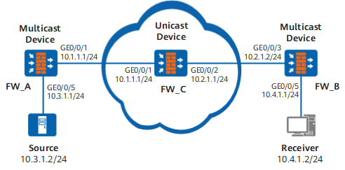
Configuration Roadmap
The configuration roadmap is as follows:
Configure an IP address for each interface.
Establish a Generic Routing Encapsulation (GRE) tunnel between FW_A and FW_B.
Configure OSPF to interconnect FW_A, FW_B, and FW_C in unicast mode.
Enable multicast on FW_A and FW_B, PIM-DM on each interface, and IGMP on the interface connected to hosts.
Configure a static multicast Reverse Path Forwarding (RPF) route on FW_B and specify FW_A as the RPF neighbor.
Procedure
- Configure an IP address for each interface.
Configure an IP address and mask for each interface as shown in Figure 1.
On FW_A:
# Assign an IP address to GigabitEthernet 0/0/1.
<FW_A> system-view
[FW_A] interface GigabitEthernet 0/0/1
[FW_A-GigabitEthernet0/0/1] ip address 10.1.1.1 24
[FW_A-GigabitEthernet0/0/1] quit
# Assign an IP address to GigabitEthernet 0/0/5.
[FW_A] interface GigabitEthernet 0/0/5
[FW_A-GigabitEthernet0/0/5] ip address 10.3.1.1 24
[FW_A-GigabitEthernet0/0/5] quit
On FW_B:
# Assign an IP address to GigabitEthernet 0/0/5.
<FW_B> system-view
[FW_B] interface GigabitEthernet 0/0/5
[FW_B-GigabitEthernet0/0/5] ip address 10.4.1.1 24
[FW_B-GigabitEthernet0/0/5] quit
# Assign an IP address to GigabitEthernet 0/0/3.
[FW_B] interface GigabitEthernet 0/0/7
[FW_B-GigabitEthernet0/0/3] ip address 10.1.4.1 24
[FW_B-GigabitEthernet0/0/3] quit
On FW_C:
# Assign an IP address to GigabitEthernet 0/0/1.
[FW_C] interface GigabitEthernet 0/0/1
[FW_C-GigabitEthernet0/0/1] ip address 10.1.1.1 24
[FW_C-GigabitEthernet0/0/1] quit
# Assign an IP address to GigabitEthernet 0/0/2.
<FW_C> system-view
[FW_C] interface GigabitEthernet 0/0/2
[FW_C-GigabitEthernet0/0/2] ip address 10.2.1.1 24
[FW_C-GigabitEthernet0/0/2] quit
- Establish a GRE tunnel between FW_A and FW_B.
# Configure FW_A.
[FW_A] interface tunnel 1/0/1[FW_A-Tunnel1/0/1] ip address 10.5.1.1 24[FW_A-Tunnel1/0/1] tunnel-protocol gre[FW_A-Tunnel1/0/1] source 10.1.1.1[FW_A-Tunnel1/0/1] destination 10.2.1.2[FW_A-Tunnel1/0/1] quit# Configure FW_B.
[FW_B] interface tunnel 1/0/1[FW_B-Tunnel1/0/1] ip address 10.5.1.2 24[FW_B-Tunnel1/0/1] tunnel-protocol gre[FW_B-Tunnel1/0/1] source 10.2.1.2[FW_B-Tunnel1/0/1] destination 10.1.1.1[FW_B-Tunnel1/0/1] quit - Configure OSPF to interconnect FW_A, FW_B, and FW_C.
# Configure OSPF on FW_A.
[FW_A] ospf 1[FW_A-ospf-1] area 0[FW_A-ospf-1-area-0.0.0.0] network 10.3.1.0 0.0.0.255[FW_A-ospf-1-area-0.0.0.0] network 10.1.1.0 0.0.0.255[FW_A-ospf-1-area-0.0.0.0] network 10.5.1.1 0.0.0.255[FW_A-ospf-1-area-0.0.0.0] quit[FW_A-ospf-1] quit# Configure OSPF on FW_B.
[FW_B] ospf 1[FW_B-ospf-1] area 0[FW_B-ospf-1-area-0.0.0.0] network 10.2.1.0 0.0.0.255[FW_B-ospf-1-area-0.0.0.0] network 10.4.1.0 0.0.0.255[FW_B-ospf-1-area-0.0.0.0] network 10.5.1.2 0.0.0.255[FW_B-ospf-1-area-0.0.0.0] quit[FW_B-ospf-1] quit# Configure OSPF on FW_C.
[FW_C] ospf 1[FW_C-ospf-1] area 0[FW_C-ospf-1-area-0.0.0.0] network 10.1.1.0 0.0.0.255[FW_C-ospf-1-area-0.0.0.0] network 10.2.1.0 0.0.0.255[FW_C-ospf-1-area-0.0.0.0] quit[FW_C-ospf-1] quit - Enable multicast on FW_A and FW_B and enable PIM-DM on each interface.
# Enable multicast on FW_A and FW_B, enable PIM-DM on each interface, and enable IGMP on the interface connected to hosts.
# Configure FW_A.
[FW_A] multicast routing-enable[FW_A] interface GigabitEthernet 0/0/5
[FW_A-GigabitEthernet0/0/5] pim dm
[FW_A-GigabitEthernet0/0/5] quit
[FW_A] interface GigabitEthernet 0/0/1
[FW_A-GigabitEthernet0/0/1] pim dm
[FW_A-GigabitEthernet0/0/1] quit
[FW_A] interface tunnel 1/0/1[FW_A-Tunnel1/0/1] pim dm[FW_A-Tunnel1/0/1] quit# Configure FW_B.
[FW_B] multicast routing-enable[FW_B] interface GigabitEthernet 0/0/3
[FW_B-GigabitEthernet0/0/3] pim dm
[FW_B-GigabitEthernet0/0/3] quit
[FW_B] interface GigabitEthernet 0/0/5
[FW_B-GigabitEthernet0/0/5] pim dm
[FW_B-GigabitEthernet0/0/5] igmp enable
[FW_B-GigabitEthernet0/0/5] quit
[FW_B] interface tunnel 1/0/1[FW_B-Tunnel1/0/1] pim dm[FW_B-Tunnel1/0/1] quit - Configure a static multicast route.
Configure a static multicast RPF route on FW_B and specify FW_A as the RPF neighbor.
[FW_B] ip rpf-route-static 10.3.1.0 255.255.255.0 10.5.1.1 - Verify the configuration.
Source 10.3.1.2/24 sends multicast data to G 225.1.1.1. The receiver joins G, and can receive multicast data sent by Source1. Run the display pim routing-table command on FW_B to check the routing table.
<FW_B> display pim routing-tableVPN-Instance: public net
Total 0 (*, G) entry; 1 (S, G) entry
(10.3.1.2, 225.1.1.1)
Protocol: pim-dm, Flag: ACT
UpTime: 00:13:29
Upstream interface: Tunnel1/0/1
Upstream neighbor: 10.5.1.1
RPF prime neighbor: 10.5.1.1
Downstream interface(s) information:
Total number of downstreams: 1
1: GigabitEthernet0/0/5Protocol: pim-dm, UpTime: - , Expires: -
Configuration Scripts
Configuration script of FW_A
#
sysname FW_A#
multicast routing-enable
#
interface GigabitEthernet0/0/1ip address 10.1.1.1 255.255.255.0
pim dm
#
interface GigabitEthernet0/0/5ip address 10.3.1.1 255.255.255.0
pim dm
#
interface Tunnel1/0/0
ip address 10.5.1.1 255.255.255.0
tunnel-protocol gre
source 10.1.1.1
destination 10.2.1.2
pim dm
#
ospf 1
area 0.0.0.0
network 10.3.1.0 0.0.0.255
network 10.1.1.0 0.0.0.255
network 10.5.1.1 0.0.0.255
#
return
Configuration script of FW_B
#
sysname FW_B#
multicast routing-enable
#
interface GigabitEthernet0/0/5ip address 10.4.1.1 255.255.255.0
pim dm
igmp enable
#
interface GigabitEthernet0/0/3ip address 10.2.1.2 255.255.255.0
pim dm
#
interface Tunnel1/0/0
ip address 10.5.1.2 255.255.255.0
tunnel-protocol gre
source 10.2.1.2
destination 10.1.1.1
pim dm
#
ospf 1
area 0.0.0.0
network 10.4.1.0 0.0.0.255
network 10.2.1.0 0.0.0.255
network 10.5.1.1 0.0.0.255
#
ip rpf-route-static 10.3.1.0 255.255.255.0 10.5.1.1
#
return
Configuration script of FW_C
#
sysname FW_C#
interface GigabitEthernet0/0/1ip address 10.1.1.2 255.255.255.0
#
interface GigabitEthernet0/0/3ip address 10.2.1.1 255.255.255.0
#
ospf 1
area 0.0.0.0
network 10.1.1.0 0.0.0.255
network 10.2.1.0 0.0.0.255
#
return