Understanding DNS Transparent Proxy
This section describes the overview, policy, and process of DNS transparent proxy.
Overview
To access web servers through domain names, intranet users need to send DNS request packets to the DNS server for domain name resolution. An enterprise rents multiple ISP links as network egresses, and each ISP network deploys the same Web servers. Generally speaking, the same DNS server address is configured on the clients of all intranet users. The DNS server then resolves domain names to the address of the Web server on the same ISP network. Therefore, the Internet access traffic from all intranet users is forwarded on the same ISP link, causing link congestion and compromising users' Internet access experiences. At the same time, other ISP links are not used, causing resource waste.
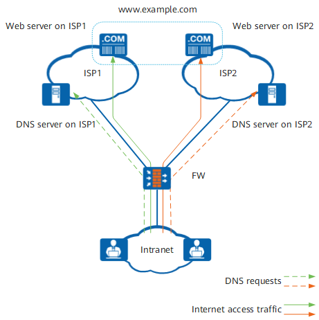
DNS transparent proxy can solve the preceding problem. For a DNS request packet that matches the DNS transparent proxy policy, the FW changes the destination address (DNS server address) of the request packet to the address of a DNS server in an ISP corresponding to the outbound interface selected by the DNS request packet. DNS request packets selecting different outbound interfaces are forwarded to different ISPs, so the resolved web server addresses belong to different ISPs. As shown in Figure 1, Internet access traffic is forwarded through different ISP links, making full use of link resources.
DNS Transparent Proxy Policy
An administrator determines which DNS requests require DNS transparent proxy based on a DNS transparent proxy policy. As the policy is matched based only on the source and destination addresses of the DNS requests. The source and destination addresses are optional. If they are not selected, the default value is any, indicating that the DNS transparent proxy policy matches DNS request packets with any source and destination addresses.
If all matching conditions configured in the DNS transparent proxy policy are matched, the traffic matches the DNS transparent proxy policy and the configured action is performed. Actions include proxy and no-proxy.
The matching conditions are logically ANDed. A packet matches a DNS transparent proxy policy only when all attributes of the packet match all conditions of the policy. If a condition has multiple values, the values are logically ORed. A packet matches the condition if the packet matches any value of the condition. If the FW has multiple DNS transparent proxy policies, DNS request packets are matched from the policy that is first configured. As long as one policy is matched, the action specified in this policy is taken and the policy matching stops. Therefore, you are advised to first configure policies with narrow matching scopes.
In addition, the system has a default DNS transparent proxy policy, which is at the bottom of the policy list and has the lowest priority. In the default policy, all conditions are set to any and action is set to no-proxy. If all configured policies are not matched, the default DNS transparent proxy policy is matched.
Procedure
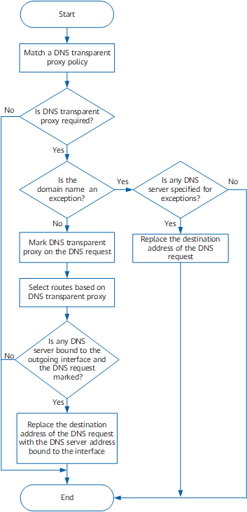
Figure 2 shows how DNS transparent proxy processes the packet from an intranet user to a specific domain name.
The process is described as follows:
When a DNS request matches a DNS transparent proxy policy, if the DNS request requires DNS transparent proxy, the FW first checks whether the domain name is an exception. If so, the FW does not perform DNS transparent proxy. If not, the FW marks DNS transparent proxy on the DNS request for the subsequent process.
For an exception, if another DNS server is required to parse this domain name, the FW changes the destination address of the DNS request to the desired DNS server address.
The DNS request selects an outbound interface based on intelligent uplink selection or common static or dynamic route selection.
One of the following modes can be selected:The priorities of route selection modes are as follows: intelligent uplink selection mode configured for the DNS transparent proxy > PBR-based intelligent uplink selection > global route selection policy > common static or dynamic route selection. By default, DNS transparent proxy selects a route based on the global route selection mode, that is, PBR-based intelligent uplink selection or global route selection policy. If intelligent uplink selection is not configured, common static or dynamic route selection is applied.
A maximum of two DNS servers can be bound to each outgoing interface on the FW, with one primary DNS server and the other secondary DNS server. Both DNS servers belong to the ISP network directly connected to the outgoing interface. After the FW determines the outgoing interface of the DNS request, the DNS transparent proxy function preferentially replaces the destination address of the DNS request with the primary DNS server address. The secondary DNS server address is used only when the primary DNS server is Down. The health check configured in DNS transparent proxy specifies whether the DNS server bound to the outbound interface is available. If both the primary and secondary DNS servers are unavailable, DNS transparent proxy does not take effect.
The FW performs DNS transparent proxy only when a DNS server is bound to the outgoing interface and the DNS request has a DNS transparent proxy mark.
Figure 3 shows the DNS transparent proxy process.
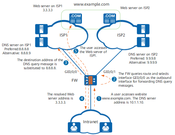
After receiving a DNS request, the FW first matches the DNS request with the DNS transparent proxy policy.
If the DNS request matches the policy, the FW selects an outgoing interface based on the route search result.
The FW replaces the destination address of the DNS request with the DNS server address bound to the outgoing interface.
The DNS server returns the parsed web server address to the user. The web server and DNS server reside on the same ISP network.
The user accesses the web server based on the returned address. The ISP Link Selection by ISP Routes function is required to ensure that the user accesses the web server through the ISP network where the web server resides, preventing cross-ISP network access.