Basic Concepts
This section describes the basic concepts and packet formats of VXLAN.
Basic Concepts
Figure 1 shows the typical architecture of a VXLAN. Layer 2 packets sent from a VM are encapsulated with UDP through a VXLAN tunnel and then sent to the peer over a Layer 3 physical network. In this way, the VXLAN tunnel enables Layer 2 packets to be forwarded across a Layer 3 network. In a VXLAN, enterprise users in various areas can plan their own virtual networks, without the need to consider restrictions of physical network IP addresses and broadcast domains. This helps reduce the difficulty in network management.
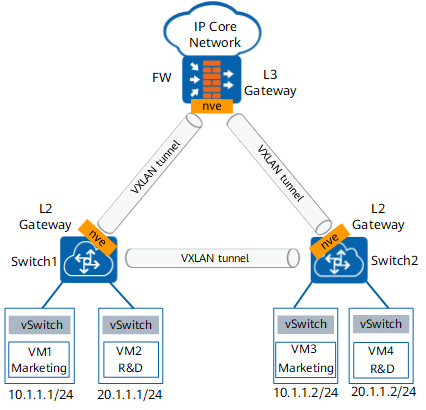
The Table 1 describes the basic concepts of VXLAN.
Name |
Description |
|---|---|
VXLAN tunnel |
A VXLAN tunnel encapsulates data packets sent from VMs into UDP packets and encapsulates IP and MAC addresses used on the physical network in outer headers before sending the packets over an IP network. The egress tunnel endpoint then decapsulates the packets and sends the packets to the destination VM. |
Network Virtualization Edge (NVE) |
An NVE node is a device that provides the VXLAN function. Either the FW or the switch in Figure 1 can be regarded as an NVE. |
VXLAN Tunnel Endpoint (VTEP) |
A VTEP is a VXLAN tunnel endpoint. For a VXLAN packet, the source IP address is the VTEP address of the local node, and the destination IP address is the VTEP address of the peer node. These two VTEP addresses correspond to a VXLAN tunnel. |
VXLAN Network Identifier (VNI) |
A VNI is similar to a VLAN ID and uniquely identifies a VXLAN segment. VMs on different VXLAN segments cannot communicate at Layer 2. A VNI represents a tenant, even if multiple terminal users belong to the same VNI. A VNI consists of 24 bits, allowing a VXLAN network to support 16 million tenants. The VNI is a global concept that takes effect across multiple devices. |
Bridge-Domain (BD) |
A BD indicates the broadcast domain of a VXLAN. The BD is associated with the VNI. Binding the VLAN with the BD on the Layer 2 service access device on the VXLAN enables the mapping from the local VLAN to the global VNI. The BD is a local concept. That is, BD1 of device1 has no relationship with BD1 of device2. |
Bridge-Domain Interface (BDIF) |
A BDIF is a Layer 3 logical interface created in a BD. The IP address configured for a BDIF is the gateway address of a VXLAN. You can configure IP addresses for BDIFs to enable communication between VXLANs of various network segments and between VXLANs and non-VXLANs. |
Gateway |
A VXLAN gateway enables communication between VXLANs and between VXLANs and non-VXLANs. Based on the network location, VXLAN gateways fall into two types:
NOTE:
The FW can serve only as a Layer 3 VXLAN gateway. |
Packet Format
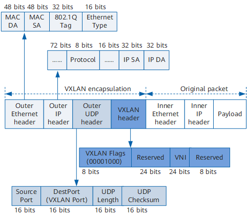
VXLAN is a network virtualization technology that uses MAC-in-UDP to encapsulate packets. That is, VXLAN adds a UDP header and a VXLAN header to an Ethernet frame. Figure 2 shows the VXLAN packet format.
Name |
Description |
|---|---|
VXLAN header |
|
Outer UDP header |
|
Outer IP header |
|
Outer Ethernet header |
|