VXLAN Tunnel Mechanism
This section describes the mechanism of a static VXLAN tunnel.
Establishing a VXLAN Tunnel
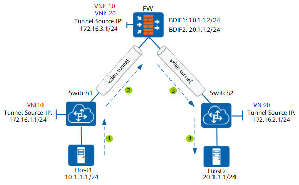
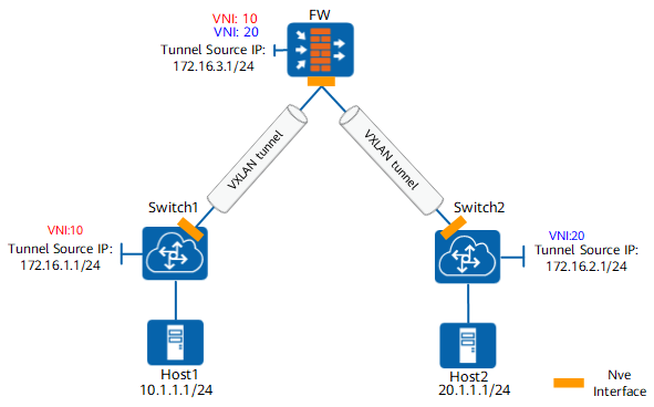
To establish a VXLAN tunnel, you need to specify the tunnel source IP address, tunnel destination IP address, and VNI information on the VXLAN gateway. Ensure that the tunnel source IP address is reachable to the tunnel destination IP address.
As shown in Figure 1, on Switch1, the tunnel source address is set to 172.16.1.1/24, tunnel destination address to 172.16.3.1/24, and VNI to 10; on the FW, the VNI is also set to 10. A VXLAN tunnel can be established between Switch1 and the FW for them to communicate with each other. Same as Switch1, Switch2 also has a VXLAN tunnel established with the FW, with the VNI being 20.
MAC Address Learning
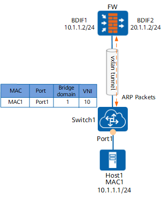
- Host1 sends an ARP request to request for the address of the Layer 3 VXLAN gateway.
- After receiving the ARP request, Switch1 updates the VXLAN MAC address table and sends the request to the FW through the VXLAN tunnel corresponding to VNI10.
To be specific, Switch1 obtains the bound Bridge domain1 based on the configuration of the incoming Port1 and then finds out VNI10 based on the bridge domain.
- After receiving the ARP request, the FW returns the MAC address of the BDIF interface corresponding to VNI10 to Switch1.
The FW has two BDIF interfaces, namely BDIF1 and BDIF2. BDIF1 corresponds to VNI10 and serves as the gateway of Host1, whereas BDIF2 corresponds to VNI20 and serves as the gateway of Host2. Access traffic between Host1 and Host2 needs to be forwarded through these two logical interfaces.
- Switch1 returns the MAC address of the BDIF1 interface to Host1.
In this way, Host1 learns the MAC address of the BDIF1 interface on the Layer 3 VXLAN gateway. The process for Host2 to learn the MAC address of the BDIF2 interface is the same and therefore not described.
Packet Forwarding
Host1 sends a service packet to Switch1.
Switch1 obtains the bound Bridge domain1 based on the configuration of the incoming Port1, finds out VNI10 based on the bridge domain, and then sends the packet to the FW through the VXLAN tunnel corresponding to VNI10.
The FW first decapsulates the packet and then sends the packet to Host2 through the VXLAN tunnel corresponding to VNI20 based on the route to Host2.
Switch2 sends the packet to Host2 based on the MAC address table.
After receiving the service packet from Host1, Host2 returns a response packet. The process for forwarding the response packet is opposite to the preceding process and therefore not described.