Mechanism of PoE
This section describes the mechanism of PoE.
Components of the PoE Power Supply System
- Power-sourcing equipment (PSE): A PoE device supplies power to
PDs through the Ethernet. It provides functions such as detection,
analysis, and intelligent power management.
According to the IEEE standards, PSEs are classified into MidSpan (PoE function module outside the device) and Endpoint (PoE function module integrated into the device). A FW can integrate the PoE function module, so it is an Endpoint PSE.
A PSE supplies power to a PD through 1/2 and 3/6 line pairs of an Ethernet cable. Lines 1 and 2 are linked to form the positive electrode, and lines 3 and 6 are linked to form the negative electrode to transmit data. DC power and data frequency do not interfere with each other. Therefore, the current and data can be transmitted through the same line pair.
- Powered device (PD): A device receives power from a PSE. Terminals such as wireless APs, portable device chargers, card readers, and cameras are PDs. PDs are classified into standard PDs and non-standard PDs, determined by their compliance with IEEE standards.
The following figure shows the FW PoE power supply system.
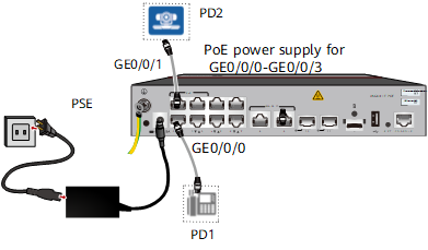
Process of PoE Power Supply
According to IEEE 802.3af and IEEE 802.3at, a PSE must detect and classify a network terminal in a certain period of time, and then determine whether to supply power to the terminal and the output power. This prevents PoE-incompatible network devices from being damaged by the 48 V power supply. Therefore, the main function of a PSE is to check whether there are compatible devices (PDs) connected to the system or disconnected from the system, and classify the power of the PDs to provide appropriate power supply or cut off the power supply.
The following figure shows the power supply process when a PSE connects to a PD.
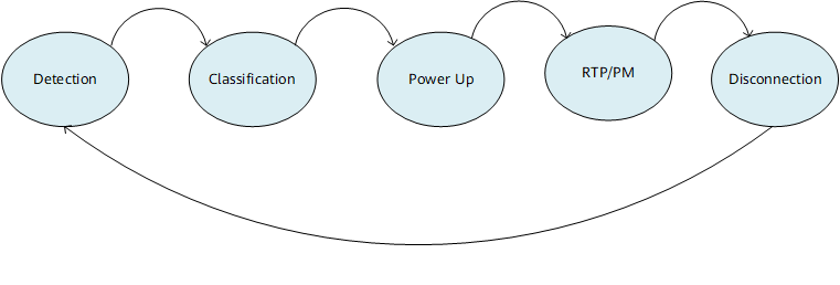
State |
Function |
Remarks |
|---|---|---|
Detection |
The PSE detects PDs. By checking the resistance and capacitance between the power output line pairs of an interface, the PSE determines whether a PD is connected to the interface. |
The process goes on only after a valid PD is detected. If the following conditions are met, a PD is connected to the
PSE:
|
Classification |
The PSE determines the PD's power consumption. The PSE determines the PD power level by detecting the output current of the power supply. Each power level corresponds to a power value. |
Table 2 lists power levels. |
Powerup |
When detecting a valid PD, the PSE determines the power level of the PD. The PSE then supplies power to the PD according to its power level. |
- |
RTP/PM RTP is short for Real-Time Transport Protocol; PM is short for Power Management. |
When supplying power, the PSE checks whether the PD is disconnected in real time. |
Output voltage: 48 V |
Disconnection |
If the PD is disconnected, the PSE shuts down the output voltage of the interface. The interface state returns to Detection. |
- |