IS-IS Routing Information Control
In practice, the routes calculated by using the shortest path first (SPF) algorithm in Intermediate System to Intermediate System (IS-IS) cannot meet all carrier requirements. For example, generating too many routing entries slows down route search, or link usage is unbalanced. Because of these problems, IS-IS routing cannot meet carriers' network planning and traffic management requirements.
- Route Leaking
- Route Summarization
- Load Balancing
- Administrative Tag
- IS-IS Mesh Group
Route Leaking
When Level-1 and Level-2 areas both exist on an IS-IS network, all Level-1 routing information (except for default routes) can advertise to Level-2 area while Level-2 routers do not advertise the learned routing information about a Level-1 area and the backbone area to any other Level-1 area. Therefore, Level-1 routers do not know the routing information outside the local area. As a result, the Level-1 routers cannot select the optimal routes to the destination outside the area.
Route leaking allows you to define access control lists (ACLs), routing policies, and tags on Level-1-2 routers so that Level-1-2 routers can select eligible routes. In this manner, a Level-1-2 router can advertise some routing information about other Level-1 areas and the backbone area to its Level-1 area. Figure 1 shows the typical networking for route leaking.
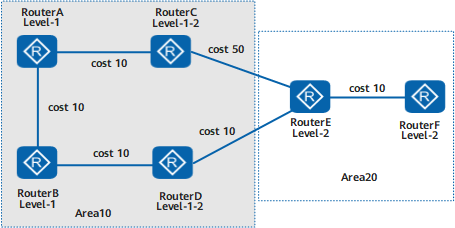
Router A, Router B, Router C, and Router D belong to area 10. Router A and Router B are Level-1 routers. Router C and Router D are Level-1-2 routers.
Router E and Router F belong to area 20 and are Level-2 routers.
If Router A sends a packet to Router F, the optimal route should be Router A -> Router B -> Router D -> Router E -> Router F. This is because the cost of the route is 40 (10 + 10 + 10 + 10 = 40). On Router A, view the route along which packets are transmitted to Router F. The selected route is Router A -> Router C -> Router E -> Router F, of which the cost is 70 (10 + 50 + 10 = 70). The route is not an optimal route from Router A to Router F.
This is because Router A does not know the routes outside the local area, so the packets sent by Router A to other network segments are sent through the default route generated by the nearest Level-1-2 router.
Enable route leaking on Level-1-2 routers (Router C and Router D) and view the route from Router A to Router F. The selected route is Router A -> Router B -> Router D -> Router E -> Router F. The route is the optimal route from Router A to Router F.
Route Summarization
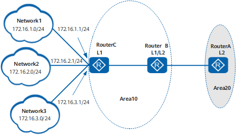
RouterA, RouterB, and RouterC use IS-IS to communicate with each other.
RouterA belongs to area 20, and RouterB and RouterC belong to area 10.
RouterA is a Level-2 router. RouterB is a Level-1-2 router. RouterC is a Level-1 router.
RouterB maintains Level-1 and Level-2 link state databases (LSDBs) and leaks the routes in three network segments (172.16.1.0/24, 172.16.2.0/24, and 172.16.3.0/24) in the Level-1 area to the Level-2 area. A link fault causes the RouterC interface with the IP address in the network segment 172.16.1.1/24 to frequently alternate between Up and Down. The status change is advertised to the Level-2 area, triggering frequent Link State Packet (LSP) flooding and SPF calculation on RouterA. As a result, the CPU usage on RouterA increases and even network flapping occurs.
On RouterB, the summarization of the routes in three network segments (172.16.1.0/24, 172.16.2.0/24, and 172.16.3.0/24) in the Level-1 area to one route in network segment 172.16.0.0/16 reduces the number of routing entries on RouterB and minimizes the impact of route flapping in the Level-1 area on route convergence in the Level-2 area.
Load Balancing
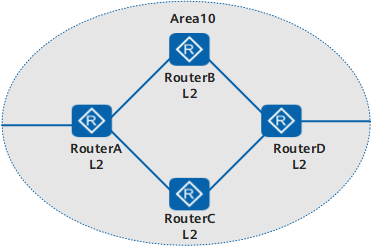
Router A, Router B, Router C, and Router D communicate with each other on an IP network using IS-IS.
Router A, Router B, Router C, and Router D belong to area 10 and are Level-2 routers.
If load balancing is not enabled, traffic on Router A is transmitted along the optimal route after SPF calculation. Consequently, traffic on different links is unbalanced. Enabling load balancing on Router A sends traffic to Router D through Router B and Router C. This transmission mode relieves the load on the optimal route.
Administrative Tag
Administrative tags carry administrative information about IP address prefixes. When the cost type is wide, wide-compatible, or compatible and the prefix of the reachable IP address to be advertised by IS-IS has this cost type, IS-IS adds the administrative tag to the reachability type-length-value (TLV) in the prefix. In this manner, the administrative tag is advertised throughout the entire IS-IS area, which implements route import or filtering.
IS-IS Mesh Group
As defined in IS-IS, a router must flood the received LSP to all neighbors. On a network with multiple connections and point-to-point (P2P) links, this flooding method causes repeated LSP flooding and wastes bandwidth.
To avoid this situation, you can add certain interfaces to a mesh group. These interfaces do not flood the LSPs received from a group to other interfaces in the same group, but flood them outside the group or to the interfaces that are not configured with the mesh group. All the interfaces that join a mesh group ensure the synchronization of the LSDBs in the entire network segment by using the complete sequence numbers protocol data unit (CSNP) and partial sequence numbers protocol data unit (PSNP) mechanisms.