Web: Example for Configuring OSPF Virtual Links
In some cases, non-backup areas cannot be physically connected to the backbone area. You can configure a virtual link for an ABR that is not directly connected to the backbone area to establish a tunnel to the backbone area.
Networking Requirements
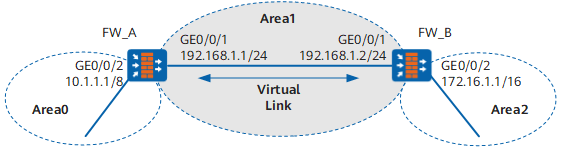
As shown in Figure 1, Area 2 is not directly connected to the backbone area. Area 1 serves as a transit area to connect Area 2 and Area 0. A virtual link between FW_A and FW_B needs to be configured.
Configuration Roadmap
The configuration roadmap is as follows:
- Enable OSPF and configure basic OSPF functions on each FW.
- Configure a virtual link between FW_A and FW_B to connect a non-backbone area to the backbone area.
Data Planning
To implement the configuration, you need to collect the following data:
- OSPF router ID of FW_A (1.1.1.1), area numbers (Area 0 and Area 1), and network segment where OSPF is enabled (192.168.1.0/24, 10.0.0.0/8).
- OSPF router ID of FW_B (2.2.2.2), area numbers (Area 1 and Area 2), and network segment where OSPF is enabled (192.168.1.0/24, 172.16.0.0/16).
Procedure
- Configure FW_A.
- Set interface IP addresses and assign the interfaces to security zones.
- Choose .
Click
 of GE0/0/1 and set required parameters.
Zone
Trust
IPv4
IP Address
192.168.1.1/24
- Click OK.
Repeat the preceding steps to configure GE GigabitEthernet0/0/2 based on the parameters in the following table.
Zone
Trust
IPv4
IP Address
10.1.1.1/8
- Configure basic OSPF functions.
Choose .
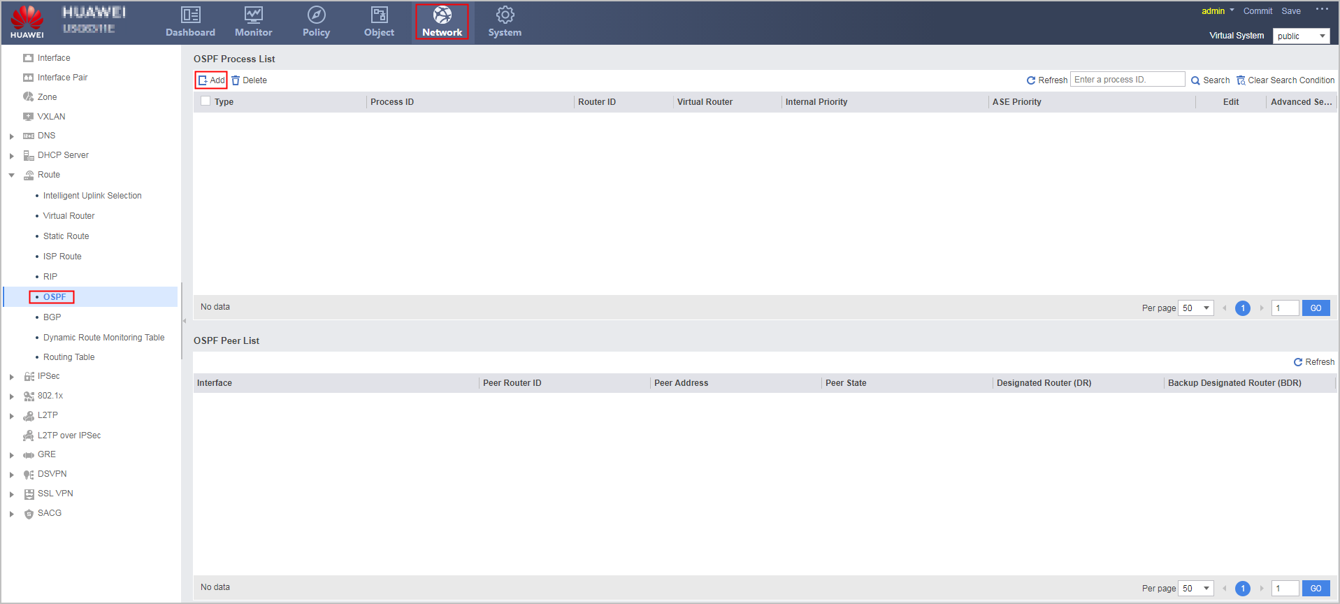
Click Add to create an OSPF process.
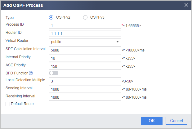
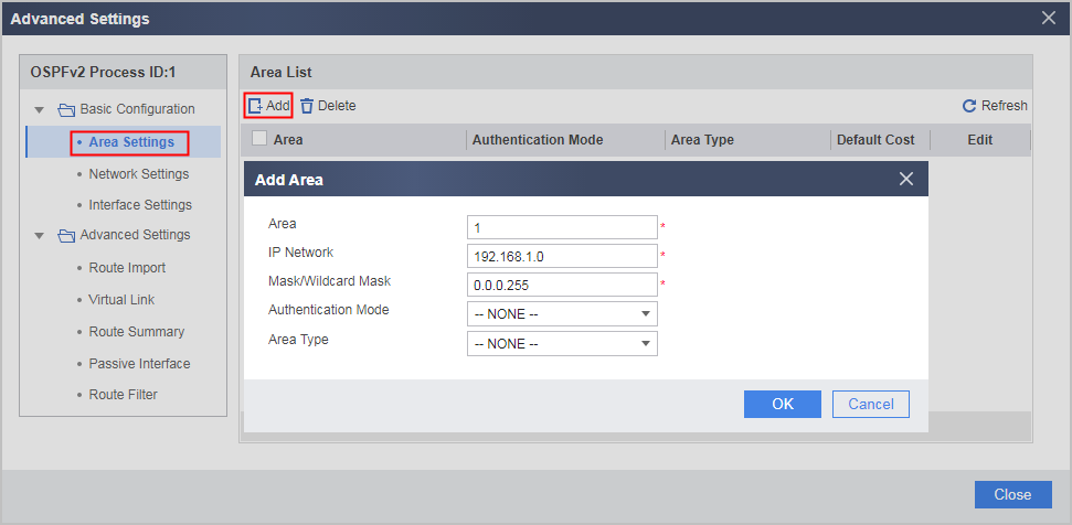
Configure the area where network segment 192.168.1.0 as Area 1.
- Click
 of the created OSPF process.
 - In the OSPFv2 Process ID:1 navigation tree, choose .
- Click Add and configure the area where network segment 192.168.1.0 resides as Area 1.
- Click OK.
- Click
Repeat the preceding steps to configure the area where network segment 10.0.0.0 resides as Area 0.
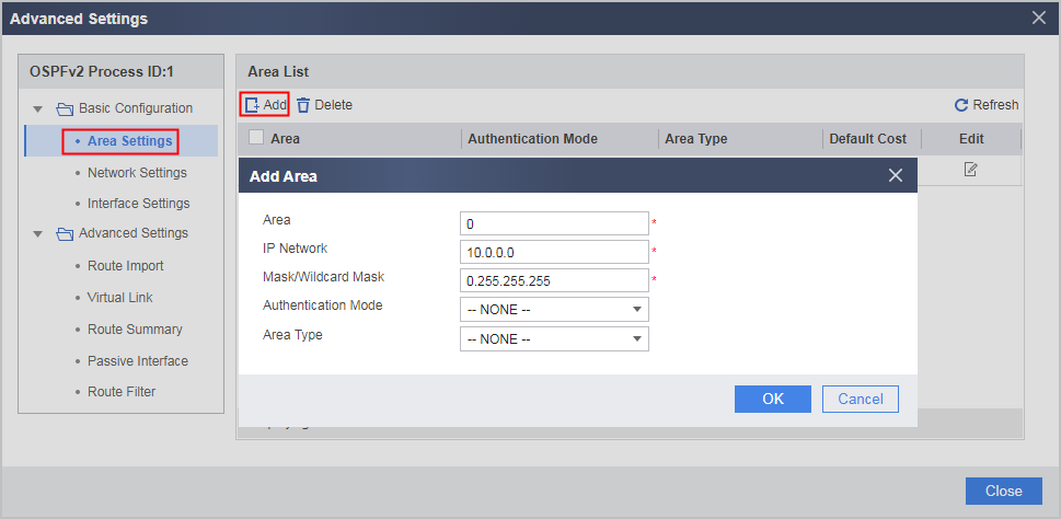
- Configure a virtual link.
- Click of the created OSPF process.
- In the OSPFv2 Process ID:1 navigation tree, choose .
- Click Add and configure a virtual link.
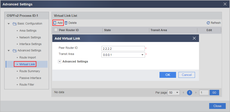
- Click OK.
- Click
- Set interface IP addresses and assign the interfaces to security zones.
- Configure FW_B.
Verification
Before a virtual link is configured:
# Check OSPF routing table of FW_A.
<FW_A> display ospf routing

          OSPF Process 1 with Router ID 1.1.1.1
                   Routing Tables

 Routing for Network
 Destination        Cost  Type       NextHop         AdvRouter       Area
 10.0.0.0/8         1     Stub       10.1.1.1        1.1.1.1         0.0.0.0
 192.168.1.0/24     1     Transit    192.168.1.1     1.1.1.1         0.0.0.1

 Total Nets: 2
 Intra Area: 2  Inter Area: 0  ASE: 0  NSSA: 0

The routing table of FW_A does not have the route to Area 2 because Area 2 is not directly connected to Area 0.
After a virtual link is configured:
# Check OSPF routing table of FW_A.
[FW_A] display ospf routing

          OSPF Process 1 with Router ID 1.1.1.1
                   Routing Tables

 Routing for Network
 Destination        Cost  Type       NextHop         AdvRouter       Area
 172.16.1.1/32      2     Inter-area 192.168.1.2     2.2.2.2         0.0.0.0
 10.0.0.0/8         1     Stub       10.1.1.1        1.1.1.1         0.0.0.0
 192.168.1.0/24     1     Transit    192.168.1.1     1.1.1.1         0.0.0.1

 Total Nets: 3
 Intra Area: 2  Inter Area: 1  ASE: 0  NSSA: 0
Configuration Scripts
Configuration script of FW_A
#
 sysname FW_A
#
interface GigabitEthernet0/0/1
 undo shutdown
 ip address 192.168.1.1 255.255.255.0
#
interface GigabitEthernet0/0/2
 undo shutdown
 ip address 10.1.1.1 255.0.0.0
#
firewall zone trust
 set priority 85
 add interface GigabitEthernet0/0/1
 add interface GigabitEthernet0/0/2
#
security-policy
 rule name policy_sec_1
  source-zone local
  source-zone trust
  destination-zone local
  destination-zone trust
  action permit
#
ospf 1 router-id 1.1.1.1
 area 0.0.0.0
  network 10.0.0.0 0.255.255.255
 area 0.0.0.1
  network 192.168.1.0 0.0.0.255
  vlink-peer 2.2.2.2
#
return
Configuration script of FW_B
#
 sysname FW_B
#
interface GigabitEthernet0/0/1
 undo shutdown
 ip address 192.168.1.2 255.255.255.0
#
interface GigabitEthernet0/0/2
 undo shutdown
 ip address 172.16.1.1 255.255.0.0
#
firewall zone trust
 set priority 85
 add interface GigabitEthernet0/0/1
 add interface GigabitEthernet0/0/2
#
security-policy
 rule name policy_sec_1
  source-zone local
  source-zone trust
  destination-zone local
  destination-zone trust
  action permit
#
ospf 1 router-id 2.2.2.2
 area 0.0.0.1
  network 192.168.1.0 0.0.0.255.
  vlink-peer 1.1.1.1
 area 0.0.0.2
  network 172.16.0.0 0.0.255.255
#
return