OSPF VPN
This section describes the definition, the purpose and the principle of OSPF VPN.
Definition
As an extension of OSPF, OSPF VPN multi-instance enables Provider Edges (PEs) and Customer Edges (CEs) in VPNs to run OSPF for interworking and use OSPF to learn and advertise routes.
Purpose
As a widely used IGP, in most cases, OSPF runs in VPNs. If OSPF runs between PEs and CEs, and PEs use OSPF to advertise VPN routes to CEs, no other routing protocols need to be configured on CEs for interworking with PEs, which simplifies management and configuration of CEs.
Running OSPF Between PEs and CEs
In BGP/MPLS VPN, Multi-Protocol BGP (MP-BGP) is used to transmit routing information between PEs, while OSPF is used to learn and advertise routes between PEs and CEs.
Running OSPF between PEs and CEs has the following benefits:
OSPF is used in a site to learn routes. Running OSPF between PEs and CEs reduces the number of the protocol types that CEs must support.
Similarly,running OSPF both in a site and between PEs and CEs simplifies the work of network administrators and reduces the number of protocols that network administrators must be familiar with.
When a network using OSPF but not VPN on the backbone network begins to use BGP/MPLS VPN, running OSPF between PEs and CEs facilitates the transition.
InFigure 1, CE1, CE3, and CE4 belong to VPN 1, and the numbers following OSPF refer to the process IDs of the multiple OSPF instances running on PEs.
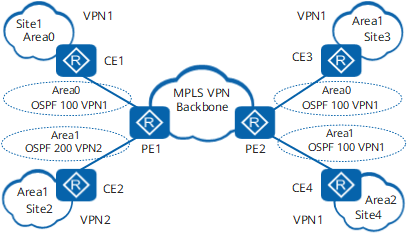
The routes that PE1 receives from CE1 are advertised to CE3 and CE4 as follows:
- PE1 imports OSPF routes of CE1 into BGP and converts them to BGP VPNv4 routes.
- PE1 uses MP-BGP to advertise the BGP VPNv4 routes to PE2.
- PE2 imports the BGP VPNv4 routes into OSPF and then advertises these routes to CE3 and CE4.
The process of advertising routes of CE4 or CE3 to CE1 is the same as the preceding process.
Configuring OSPF Areas Between PEs and CEs
OSPF areas between PEs and CEs can be non-backbone or backbone areas (area 0), and PEs can function only as ABRs.

By default, when OSPF is configured in VPN instances, the device is considered as an ASBR for each area. For this reason, if two OSPF non-backbone areas (for example area 2 and area 4) are connected by two parallel links, routes are imported between the two areas. Specifically, the routes in area 2 are advertised to area 4, and the routes in area 4 are advertised to area 2. As a result, the two areas have the same routing table. To prevent this problem, use one of the following methods:
- Filter LSAs or routes using a route-filter, route-policy, or any other filters available.
- Configure two VPN instances on each link, deploy import/export extended communities for communication, and configure two OSPF processes.
In the extended application of OSPF VPN, the MPLS VPN backbone network is considered Area 0. OSPF requires that Area 0 be contiguous. Therefore, Area 0 of all VPN sites must be connected to the MPLS VPN backbone network. If a VPN site has Area 0, the PEs that CEs access must be connected to the backbone area of this VPN site through Area 0. In this scenario, a virtual link can also be deployed between the PEs and the backbone area. Figure 2 shows the networking for configuring OSPF areas between PEs and CEs.
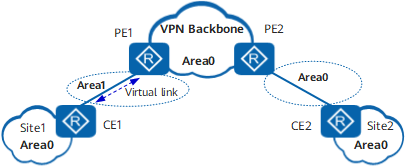
In Figure 2, a non-backbone area (Area 1) is configured between PE1 and CE1, and a backbone area (Area 0) is configured in Site 1. Then, the backbone area in Site 1 is separated from the VPN backbone area. To ensure that the backbone areas are contiguous, a virtual link is configured between PE1 and CE1.
OSPF Domain ID
If inter-area routes are advertised between local and remote OSPF areas, these areas are considered to be in the same OSPF domain.
- Domain IDs identify domains.
- Each OSPF domain has one or multiple domain IDs. If more than one domain ID is available, one of the domain IDs is a primary ID, and the others are secondary IDs.
- If an OSPF instance does not have a specific domain ID, its ID is considered as null.
Before advertising the remote routes sent by BGP to CEs, PEs need to determine the type of OSPF route (Type 3 or Type 5) to be advertised to CEs based on domain IDs.
- If local domain IDs are the same as or compatible with remote domain IDs in BGP routes, PEs advertise Type 3 routes.
- If local domain IDs are different from or incompatible with remote domain IDs in BGP routes, PEs advertise Type 5 routes.
Relationship Between Local and Remote Domain IDs |
Same or Different |
Type of the Generated Route |
|---|---|---|
Both domain IDs are null. |
Same |
Inter-area route |
The remote domain ID is the same as the local primary domain ID or one of the local secondary domain IDs. |
Same |
Inter-area route |
The remote domain ID is different from the local primary domain ID or any of the local secondary domain IDs. |
Different |
If the local area is a non-NSSA, external routes are generated. If the local area is an NSSA, NSSA routes are generated. |
Routing Loop Prevention
Routing loops may occur between PEs and CEs when OSPF and BGP learn routes from each other.
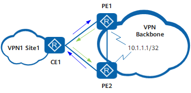
In Figure 3, on PE1, OSPF imports a BGP route destined for 10.1.1.1/32 and then generates and advertises a Type 5 or Type 7 LSA to CE1. Then, CE1 learns an OSPF route with 10.1.1.1/32 as the destination address and PE1 as the next hop and advertises the route to PE2. Therefore, PE2 learns an OSPF route with 10.1.1.1/32 as the destination address and CE1 as the next hop.
Similarly, CE1 also learns an OSPF route with 10.1.1.1/32 as the destination address and PE2 as the next hop. PE1 learns an OSPF route with 10.1.1.1/32 as the destination address and CE1 as the next hop.
As a result, CE1 has two equal-cost routes with PE1 and PE2 as next hops, respectively, and the next hops of the routes from PE1 and PE2 to 10.1.1.1/32 are CE1, which leads to a routing loop.
In addition, the priority of an OSPF route is higher than that of a BGP route. Therefore, on PE1 and PE2, BGP routes to 10.1.1.1/32 are replaced with the OSPF route, and the OSPF route with 10.1.1.1/32 as the destination address and CE1 as the next hop is active in the routing tables of PE1 and PE2.
The BGP route is inactive, and therefore, the LSA generated when this route is imported by OSPF is deleted, which causes the OSPF route to be withdrawn. As a result, no OSPF route exists in the routing table, and the BGP route becomes active again. This cycle causes route flapping.
OSPF VPN provides solutions to this problem, as described in Table 2.
Feature |
Definition |
Function |
|---|---|---|
DN-bit |
It is a flag bit used by OSPF multi-instance processes to prevent routing loops. |
After OSPF multi-instance is configured on the router (a PE or an MCE), the router sets the DN-bit of generated Type 3, Type 5, or Type 7 LSAs to 1 and retains the DN-bit (0) of other LSAs. When calculating routes, the OSPF multi-instance process on the router ignores LSAs with DN-bit 1, which prevents the router from receiving the LSAs that are advertised by itself. In Figure 3, PE1 generates Type 3, Type 5, or Type 7 LSAs, sets their DN-bit to 1, and advertises these LSAs to CE1. After receiving these LSAs, CE1 forwards them to PE2. Upon reception of these LSAs, PE2 ignores them and does not forward them back to PE1, which prevents a routing loop. |
VPN Route Tag |
The VPN route tag is carried in the Type 5 or Type 7 LSA generated by PEs based on the received BGP private route. It is not carried in BGP extended community attributes. The VPN route tag is valid only on PEs that receive BGP routes and generate OSPF LSAs. |
When a PE detects that the VPN route tag in the incoming LSA is the same as that in the local LSA, the PE ignores this LSA, which prevents routing loops. |
Default route |
It is a route whose destination IP address and mask are both 0s. |
PEs do not calculate default routes. Default routes are used to forward traffic from CEs or sites where CEs reside to the VPN backbone network. |
Sham Link
OSPF sham links are unnumbered P2P links between two PEs over an MPLS VPN backbone network.
Generally, BGP extended community attributes carry routing information over the MPLS VPN backbone between BGP peers. OSPF running on the other PE can use the routing information to generate inter-area routes from PEs to CEs.
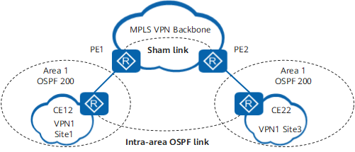
In Figure 4, if an intra-area OSPF link exists between the network segments of local and remote CEs. Routes that pass through the intra-area route link and have higher priorities than inter-area routes that pass through the MPLS VPN backbone network. As a result, VPN traffic is always forwarded through the intra-area route instead of the backbone network. To prevent such a problem, an OSPF sham link can be established between PEs so that the routes that pass through the MPLS VPN backbone network also become OSPF intra-area routes and take precedence.
A sham link is a link between two VPN instances. Each VPN instance contains the address of an end-point of a sham link. The address is a loopback address with the 32-bit mask in the VPN address space on the PE.
After a sham link is established between two PEs, the PEs become neighbors on the sham link and exchange routing information.
A sham link functions as a P2P link within an area. Users can select a route from the sham link and intra-area route link by adjusting the metric.
Multi-VPN-Instance CE
OSPF multi-instance generally runs on PEs. The routers that run OSPF multi-instance within user LANs are called Multi-VPN-Instance CEs (MCEs).
Compared with OSPF multi-instance running on PEs, MCEs have the following characteristics:
- Do not need to support OSPF-BGP association.
- Establish one OSPF instance for each service. Different virtual CEs transmit different services, which ensures LAN security at a low cost.
- Implement OSPF multi-instances on a CE. The key to implementing MCEs is to disable loop detection and calculate routes directly. MCEs also need to use the received LSAs with the DN-bit for route calculation.