OSPF Neighbor Relationship Flapping Suppression
OSPF neighbor relationship flapping suppression works by delaying OSPF neighbor relationship reestablishment or setting the link cost to the maximum value (65535).
Background
If the status of an interface carrying OSPF services alternates between Up and Down, OSPF neighbor relationship flapping occurs on the interface. During the flapping, OSPF frequently sends Hello packets to reestablish the neighbor relationship, synchronizes LSDBs, and recalculates routes. In this process, a large number of packets are exchanged, adversely affecting neighbor relationship stability, OSPF services, and other OSPF-dependent services, such as LDP and BGP. OSPF neighbor relationship flapping suppression can address this problem by delaying OSPF neighbor relationship reestablishment or preventing service traffic from passing through flapping links.
Related Concepts
Flapping_event: reported when the status of a neighbor relationship on an interface last changes from Full to a non-Full state. The flapping_event triggers flapping detection.
Flapping_count: number of times flapping has occurred.
Detect-interval: detection interval. The interval is used to determine whether to trigger a valid flapping_event.
Threshold: flapping suppression threshold. When the flapping_count reaches or exceeds threshold, flapping suppression takes effect.
Resume-interval: interval for exiting from OSPF neighbor relationship flapping suppression. If the interval between two successive valid flapping_events is longer than resume-interval, the flapping_count is reset.
Implementation
Flapping detectionEach OSPF interface on which OSPF neighbor relationship flapping suppression is enabled starts a flapping counter. If the interval between two successive neighbor status changes from Full to a non-Full state is shorter than detecting-interval, a valid flapping_event is recorded, and the flapping_count increases by 1. When the flapping_count reaches or exceeds threshold, flapping suppression takes effect. If the interval between two successive neighbor status changes from Full to a non-Full state is longer than resume-interval, the flapping_count is reset.
The detecting-interval, threshold, and resume-interval are configurable.
Flapping suppressionFlapping suppression works in either Hold-down or Hold-max-cost mode.
- Hold-down mode: In the case of frequent flooding and topology changes during neighbor relationship establishment, interfaces prevent neighbor relationships from being reestablished during the suppression period, which minimizes LSDB synchronization attempts and packet exchanges.
- Hold-max-cost mode: If the traffic forwarding path changes frequently, interfaces use 65535 as the cost of the flapping link during the suppression period, which prevents traffic from passing through the flapping link.
Flapping suppression can also work first in Hold-down mode and then in Hold-max-cost mode.
By default, the Hold-max-cost mode takes effect. The mode and suppression period can be changed manually.

Interfaces exit from flapping suppression in the following scenarios:
- The suppression timer expires.
- The corresponding OSPF process is reset.
- A command is run to exit from flapping suppression.
Typical Scenarios
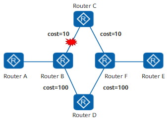
Basic scenarioIn Figure 1, the traffic forwarding path is Router A -> Router B -> Router C -> Router E before a link failure occurs. After the link between Router B and Router C fails, the forwarding path switches to Router A -> Router B -> Router D -> Router E. If the neighbor relationship between Router B and Router C frequently flaps at the early stage of the path switchover, the forwarding path will be switched frequently, causing traffic loss and affecting network stability. If the neighbor relationship flapping meets suppression conditions, flapping suppression takes effect.
- If flapping suppression works in Hold-down mode, the neighbor relationship between Router B and Router C is prevented from being reestablished during the suppression period, in which traffic is forwarded along the path Router A -> Router B -> Router D -> Router E.
- If flapping suppression works in Hold-max-cost mode, 65535 is used as the cost of the link between Router B and Router C during the suppression period, and traffic is forwarded along the path Router A -> Router B -> Router D -> Router E.
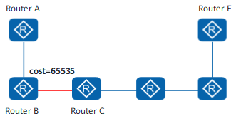
When only one forwarding path exists on the network, the flapping of the neighbor relationship between any two devices on the path will interrupt traffic forwarding. In Figure 2, the traffic forwarding path is Router A -> Router B -> Router C -> Router E. If the neighbor relationship between Router B and Router C flaps, and the flapping meets suppression conditions, flapping suppression takes effect. However, if the neighbor relationship between Router B and Router C is prevented from being reestablished, the whole network will be divided. Therefore, Hold-max-cost mode (rather than Hold-down mode) is recommended. If flapping suppression works in Hold-max-cost mode, 65535 is used as the cost of the link between Router B and Router C during the suppression period. After the network stabilizes and the suppression timer expires, the link is restored.
By default, the Hold-max-cost mode takes effect.
In Figure 3, four devices are deployed on the same broadcast network using switches, and the devices are broadcast network neighbors. If Router C flaps due to a link failure, and Router A and Router B were deployed at different time (Router A was deployed earlier for example) or the flapping suppression parameters on Router A and Router B are different, Router A first detects the flapping and suppresses Router C. Consequently, the Hello packets sent by Router A do not carry Router C's router ID. However, Router B has not detected the flapping yet and still considers Router C a valid node. As a result, the DR candidates identified by Router A are Router B and Router D, whereas the DR candidates identified by Router B are Router A, Router C, and Router D. Different DR candidates result in a different DR election result, which may lead to route calculation errors. To prevent this problem in scenarios where an interface has multiple neighbors, such as on a broadcast, P2MP, or NBMA network, all neighbors on the interface are suppressed when the status of a neighbor relationship last changes to ExStart or Down. Specifically, if Router C flaps, Router A, Router B, and Router D on the broadcast network are all suppressed. After the network stabilizes and the suppression timer expires, Router A, Router B, and Router D are restored to normal status.
Multi-area scenario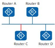
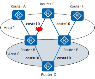
In Figure 4, Router A, Router B, Router C, Router E, and Router F are connected in area 1, and Router B, Router D, and Router E are connected in backbone area 0. Traffic from Router A to Router F is preferentially forwarded along an intra-area route, and the forwarding path is Router A -> Router B -> Router C -> Router E -> Router F. When the neighbor relationship between Router B and Router C flaps and the flapping meets suppression conditions, flapping suppression takes effect in the default mode (Hold-max-cost). Consequently, 65535 is used as the cost of the link between Router B and Router C. However, the forwarding path remains unchanged because intra-area routes take precedence over inter-area routes during route selection according to OSPF route selection rules. To prevent traffic loss in multi-area scenarios, configure Hold-down mode to prevent the neighbor relationship between Router B and Router C from being reestablished during the suppression period. During this period, traffic is forwarded along the path Router A -> Router B -> Router D -> Router E -> Router F.
By default, the Hold-max-cost mode takes effect. The mode can be changed to Hold-down manually.
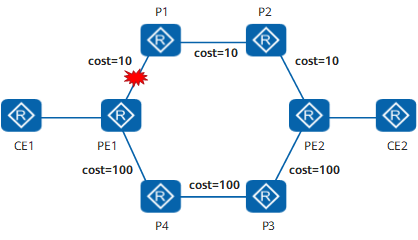
In Figure 5, if the link between PE1 and P1 fails, an LDP LSP switchover is implemented immediately, causing the original LDP LSP to be deleted before a new LDP LSP is established. To prevent traffic loss, LDP-IGP synchronization needs to be configured. With LDP-IGP synchronization, 65535 is used as the cost of the new LSP to be established. After the new LSP is established, the original cost takes effect. Consequently, the original LSP is deleted, and LDP traffic is forwarded along the new LSP.
LDP-IGP synchronization and OSPF neighbor relationship flapping suppression work in either Hold-down or Hold-max-cost mode. If both functions are configured, Hold-down mode takes precedence over Hold-max-cost mode, followed by the configured link cost. Table 1 lists the suppression modes that take effect in different situations.
| LDP-IGP Synchronization/OSPF Neighbor Relationship Flapping Suppression Mode | LDP-IGP Synchronization Hold-down Mode | LDP-IGP Synchronization Hold-max-cost Mode | Exited from LDP-IGP Synchronization Suppression |
|---|---|---|---|
OSPF Neighbor Relationship Flapping Suppression Hold-down Mode |
Hold-down |
Hold-down |
Hold-down |
OSPF Neighbor Relationship Flapping Suppression Hold-max-cost Mode |
Hold-down |
Hold-max-cost |
Hold-max-cost |
Exited from OSPF Neighbor Relationship Flapping Suppression |
Hold-down |
Hold-max-cost |
Exited from LDP-IGP synchronization and OSPF neighbor relationship flapping suppression |
For example, the link between PE1 and P1 frequently flaps in Figure 5, and both LDP-IGP synchronization and OSPF neighbor relationship flapping suppression are configured. In this case, the suppression mode is selected based on the preceding principles. No matter which mode (Hold-down or Hold-max-cost) is selected, the forwarding path is PE1 -> P4 -> P3 -> PE2.
If a link has poor link quality, services transmitted along it may be adversely affected. If bit-error-triggered protection switching is configured and the bit error rate (BER) along a link exceeds a specified value, a bit error event is reported, and 65535 is used as the cost of the link, triggering route reselection. Consequently, service traffic is switched to the backup link. If both bit-error-triggered protection switching and OSPF neighbor relationship flapping suppression are configured, they both take effect. Hold-down mode takes precedence over Hold-max-cost mode, followed by the configured link cost.