OSPFv3 Packet Format
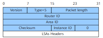
Open Shortest Path First (OSPF) for IPv6 packets are encapsulated into IPv6 packets. The OSPFv3 protocol number is 89. OSPFv3 packets are classified into the following types:
Packet Header Format
The five types of OSPFv3 packets have the same packet header format. The length of an OSPFv3 packet header is 24 bytes. Figure 1 shows an OSPFv3 packet header.
Table 1 describes packet header fields.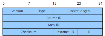
Field |
Length |
Description |
|---|---|---|
Version |
8 bits |
OSPF version number. For OSPFv3, the value is 3. |
Type |
8 bits |
OSPFv3 packet type. The values are as follows:
|
Packet length |
16 bits |
Length of the OSPFv3 packet containing the packet header, in bytes. |
Router ID |
32 bits |
ID of the router that sends the OSPFv3 packet. |
Area ID |
32 bits |
ID of the area to which the router that sends the OSPFv3 packet belongs. |
Checksum |
16 bits |
Checksum of the OSPFv3 packet that does not contain the Authentication field. |
Instance ID |
8 bits |
ID of an OSPFv3 instance. |
0 |
8 bits |
Reserved fields. |
Hello Packet
Hello packets are commonly used packets, which are periodically sent on OSPFv3 interfaces to establish and maintain neighbor relationships. A Hello packet includes information about the designated router (DR), backup designated router (BDR), timers, and known neighbors. Figure 2 shows the format of a Hello packet.
Table 2 describes Hello packet fields.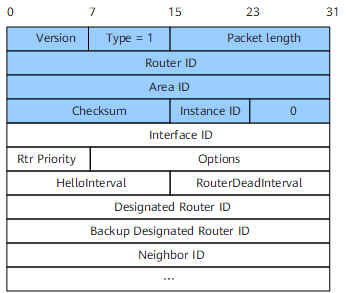
Field |
Length |
Description |
|---|---|---|
Interface ID |
32 bits |
ID of the interface that sends the Hello packets. |
Rtr Priority |
8 bits |
DR priority. The default value is 1. NOTE:
If the DR priority of a router interface is set to 0, the interface
cannot participate in a DR or BDR election. |
Options |
24 bits |
The values are as follows:
|
HelloInterval |
16 bits |
Interval at which Hello packets are sent. |
RouterDeadInterval |
16 bits |
Dead interval. If a router does not receive any Hello packets from its neighbors within a specified dead interval, the neighbors are considered Down. |
Designated Router ID |
32 bits |
Interface address of the DR. |
Backup Designated Router ID |
32 bits |
Interface address of the BDR. |
Neighbor ID |
32 bits |
Router ID of the neighbor. |
Table 3 lists the address types, interval types, and default intervals used when Hello packets are transmitted on different networks.
Network Type |
Address Type |
Interval Type |
Default Interval |
|---|---|---|---|
Broadcast |
Multicast address |
HelloInterval |
10 seconds |
Non-broadcast multiple access (NBMA) |
Unicast address |
|
30 seconds for HelloInterval 120 seconds for PollInterval |
Point-to-point (P2P) |
Multicast address |
HelloInterval |
10 seconds |
Point-to-multipoint (P2MP) |
Unicast address |
HelloInterval |
30 seconds |

DD Packet
During an adjacency initialization, two routers use DD packets to describe their own link state databases (LSDBs) for LSDB synchronization. A DD packet contains the header of each LSA in an LSDB. An LSA header uniquely identifies an LSA. The LSA header occupies only a small portion of the LSA, which reduces the amount of traffic transmitted between routers. A neighbor can use the LSA header to check whether it already has the LSA. When two routers exchange DD packets, one functions as the master and the other functions as the slave. The master defines a start sequence number. The master increases the sequence number by one each time it sends a DD packet. After the slave receives a DD packet, it uses the sequence number carried in the DD packet for acknowledgement.
Figure 3 shows the format of a DD packet.
Table 4 describes DD packet fields.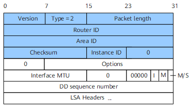
Field |
Length |
Description |
|---|---|---|
Options |
24 bits |
The values are as follows:
|
Interface MTU |
16 bits |
Maximum length of the DD packet sent by the interface with packet fragmentation disabled. |
I |
1 bit |
If the DD packet is the first packet among multiple consecutive DD packets sent by a router, this field is set to 1. In other cases, this field is set to 0. |
M (More) |
1 bit |
If the DD packet is the last packet among multiple consecutive DD packets sent by a router, this field is set to 0. In other cases, this field is set to 1. |
M/S (Master/Slave) |
1 bit |
When two routers exchange DD packets, they negotiate a master/slave relationship. The router with a larger router ID becomes the master. If this field is set to 1, the DD packet is sent by the master. |
DD sequence number |
32 bits |
Sequence number of the DD packet. The master and slave use the sequence number to ensure that DD packets are correctly transmitted. |
LSA Headers |
- |
LSA header information included in the DD packet. |
LSR Packet
After two routers exchange DD packets, they send LSR packets to request each other's LSAs. The LSR packets contain the summaries of the requested LSAs. Figure 4 shows the format of an LSR packet.
Table 5 describes LSR packet fields.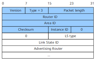
Field |
Length |
Description |
|---|---|---|
LS type |
16 bits |
Type of the LSA |
Link State ID |
32 bits |
This field together with the LS type field describes an LSA in an AS. |
Advertising Router |
32 bits |
Router ID of the router that generates the LSA. |
LSU Packet
A router uses an LSU packet to transmit LSAs requested by its neighbors or to flood its own updated LSAs. The LSU packet contains a set of LSAs. For multicast and broadcast networks, LSU packets are multicast to flood LSAs. To ensure reliable LSA flooding, a router uses an LSAck packet to acknowledge the LSAs contained in an LSU packet that is received from a neighbor. If an LSA fails to be acknowledged, the router retransmits the LSA to the neighbor. Figure 5 shows the format of an LSU packet.
Table 6 describes the LSU packet field.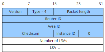
LSAck Packet
A router uses an LSAck packet to acknowledge the LSAs contained in a received LSU packet. The LSAs can be acknowledged using LSA headers. LSAck packets can be transmitted over different links in unicast or multicast mode. Figure 6 shows the format of an LSAck packet.
Table 7 describes the LSAck packet field.