Application Scenarios for SLB
The FW functioning as the security gateway can provide the SLB function to enhance service capability and user experience.
SLB for a Data Center
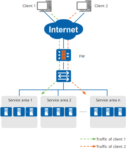
A data center comprises a set of complex devices, including computer systems, servers, environmental control devices, monitoring devices, and security devices. Servers are a key component of a data center, which achieves data processing, storage, and exchange. The FW, the security gateway of a data center, not only provides comprehensive protection, but also uses SLB to resolve long service response time and low device processing performance issues.
As shown in Figure 1, the FW resides at the network ingress of the data center and protects the network that contains server clusters using security isolation. Every server cluster constitutes a service area and provides a specific type of service. Upon receiving a service request from a client, the FW sends it to a service area based on the service type and uses the SLB function to specify the server that processes it.
SLB for an Enterprise Zone
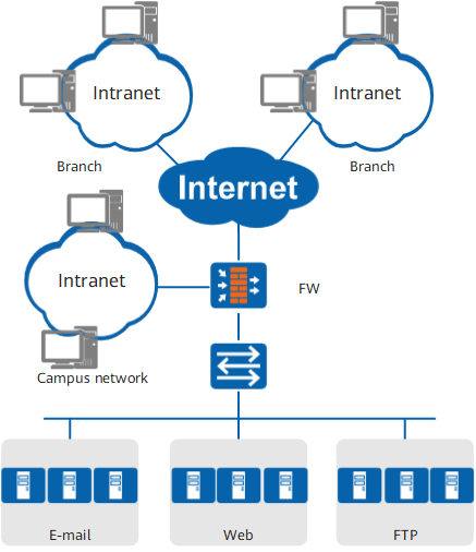
The amount of data to be processed on an enterprise network increases sharply with wide enterprise expansion and explosive service growth. Before constructing a campus network or expanding the existing network, an enterprise needs to take the service capability, investment, and even future profitability into account. The FW acts as the security gateway of the enterprise zone and protects users and server clusters in the zone using security isolation. The SLB function is configured on the FW to enable users to rapidly access enterprise resources and services and enjoy good user experience. The enterprise can expand services conveniently and reduce investment.
As shown in Figure 2, the FW resides at the network ingress of the server clusters. The users and servers on the enterprise campus network disperse in different areas. The FW uses the security policy to control user access to the server clusters. Branch users access the servers through the Internet. The FW provides these users with a security access mechanism to achieve the remote service by making full use of the servers. The servers are grouped by service type. The FW sends user traffic to a specific server group and uses the SLB function to determine the server that processes the traffic.
SLB for a Multi-Egress Server Cluster
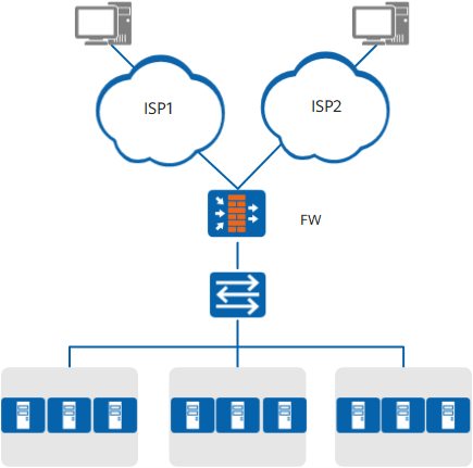
To improve service reliability, the network on which a server cluster resides usually has multiple egresses provided by different ISPs. When one ISP network connected through an egress is unavailable, users can obtain services from another ISP's network. Dual-egress is a typical multi-egress scenario.
As shown in Figure 3, the network on which the server clusters are located has two egresses. The FW serves as the security gateway and resides at the network ingress. The servers are divided into multiple groups, and each group provides the same type of service. The FW uses the SLB function to enable every group to serve ISP1 and ISP2 users. The FW sends a received service request to a group based on the service type and uses the SLB function to specify the server that processes the request. In this way, each group can serve two ISP networks, reducing investment and utilizing existing resources for cluster expansion.
SLB for the LTE IPSec Solution
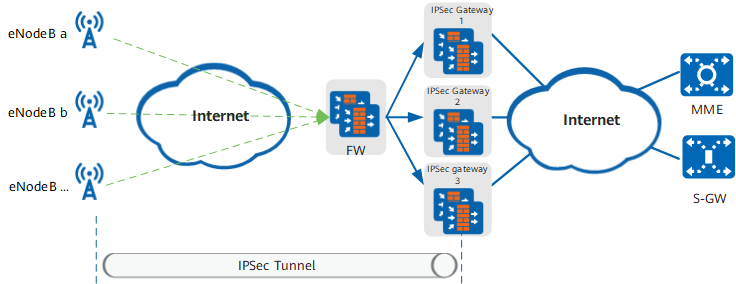
In the LTE scenario, there are many eNodeBs. With the development of 4G services, the user traffic carried by each eNodeB dramatically increases. An IPSec gateway has limited performance and is not able to carry the user traffic of all eNodeBs. Therefore, multiple IPSec gateways that work in load balancing mode are required in the LTE scenario to establish IPSec tunnels for VPN traffic transmission.
As shown in Figure 4, FWs are deployed at the access side of the eNodeBs to implement traffic load balancing so that traffic is distributed to multiple IPSec gateways. To improve reliability, the FWs work in hot standby mode.

IKE negotiation traffic is UDP traffic, and service traffic is ESP traffic. The two types of traffic are processed by the same IPSec gateway. Therefore, the sticky session function based on source IP addresses needs to be configured on the FW.