Web: Example for Configuring Load Balancing Among Existing Servers and Newly Added Servers
This example describes the configuration of HTTP server load balancing.
Networking Requirements
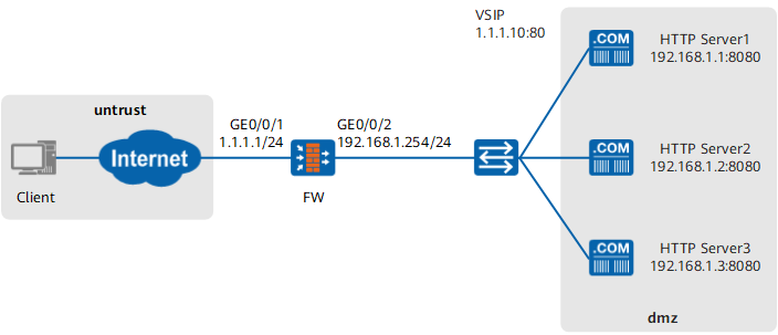
As shown in Figure 1, an enterprise has three web servers: Server1, Server2, and Server3. The hardware performance of the servers decreases in sequence. Server1 performance is twice of Server2 performance. Server2 performance is twice of Server3 performance. SLB is configured to allow the three servers to provide HTTP services as a whole. The carried services match the server hardware performance. In addition, the health check function is configured to monitor the work of the servers.
Configuration Roadmap
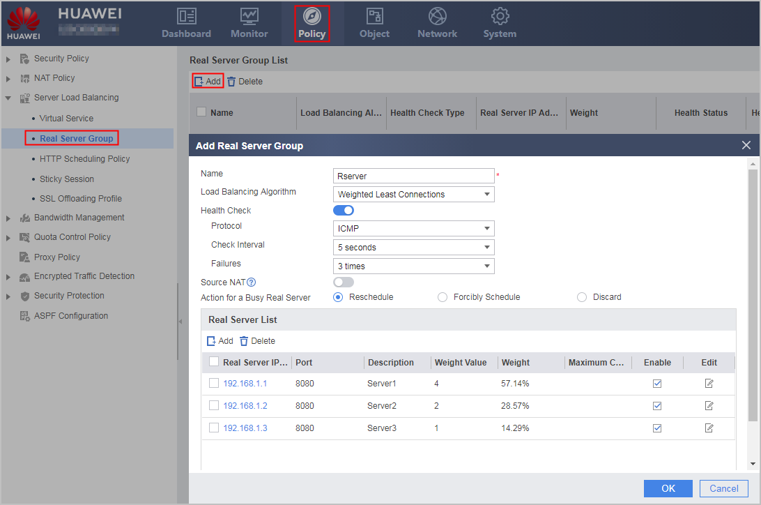
- Select Weighted Least Connections as the load balancing algorithm for performance-based SLB. As Server1 performance is twice of Server2 performance and Server2 performance is twice of Server3 performance, the weight ratio of the servers is 4:2:1.
- Configure the health check function on the FW to check server connectivity. In this example, the protocol type is set to ICMP for health check. You can also use HTTP. To allow the FW to send health check packets, configure a Local -> DMZ security policy (the servers reside in the DMZ).
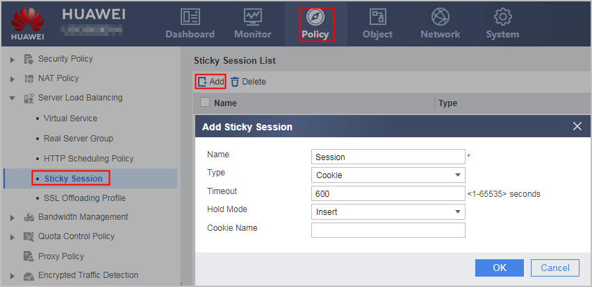
- Configure the sticky session function on the FW because a client may need to establish multiple connections to a server for one task. In this manner, the connection requests from the client can be allocated to the same server. As the servers provide HTTP services, the sticky session mode can be set to HTTP Cookie.
Procedure
- Choose to configure interface IP addresses and security zones.
Interface Name
GigabitEthernet 0/0/1
GigabitEthernet 0/0/2
Zone
untrust
DMZ
IP Address
1.1.1.1/24
192.168.1.254/24
- Choose to configure security policies.
Configure an Untrust -> DMZ security policy to allow Internet users to access intranet web servers. The destination IP address specified in the policy must be the IP address of the virtual server.
Source Zone
untrust
Destination Zone
dmz
Destination Address/Region
1.1.1.10/24
Configure a Local -> DMZ security policy to allow the FW to send health probe packets to real servers.
Source Zone
local
Destination Zone
dmz
Destination Address/Region
192.168.1.1–192.168.1.3
- Choose to configure Sticky Session.
- Choose to configure Real Server Group.
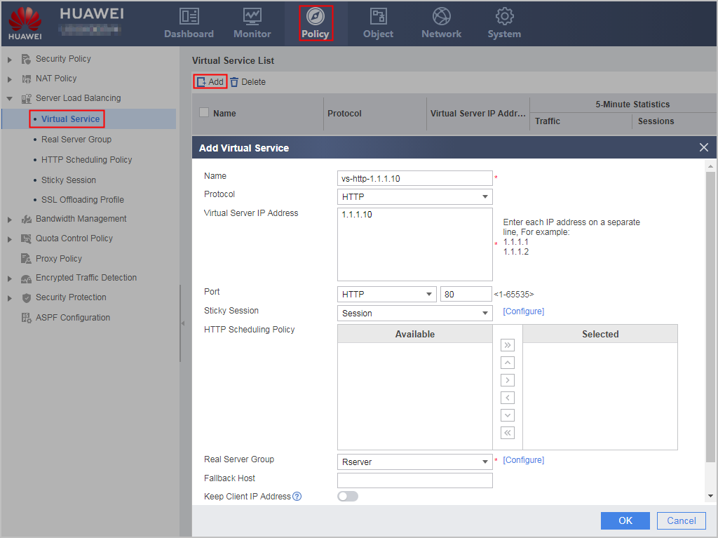
- Choose to configure Virtual Server.
Configuration Scripts
#
interface GigabitEthernet 0/0/1
 ip address 1.1.1.1 24
#
interface GigabitEthernet 0/0/2
 ip address 192.168.1.254 24
#
firewall zone untrust
 add interface GigabitEthernet 0/0/1
#
firewall zone dmz
 add interface GigabitEthernet 0/0/2
#
security-policy
 rule name policy1
  source-zone untrust
  destination-zone dmz
  destination-address 1.1.1.10 24
  action permit
 rule name policy2
  source-zone local
  destination-zone dmz
  destination-address range 192.168.1.1 192.168.1.3
  action permit
#
slb enable
#
slb
 group 0 Rserver
  metric weight-least-connection
  health-check type icmp tx-interval 5 times 3
  rserver 0 rip 192.168.1.1 port 8080 weight 4 description server1
  rserver 1 rip 192.168.1.2 port 8080 weight 2 description server2
  rserver 2 rip 192.168.1.3 port 8080 weight 1 description server3
 persistence 0 Session
  type cookie aging-time 600
 vserver 0 vs-http-1.1.1.10
  vip 0 1.1.1.10
  protocol http
  persistence Session
  vport 80
  group Rserver